6.0 Power Stroke Turbocharger Variations & Changes
All 6.0L Power Stroke engines utilize a Garrett model GT3782VA variable geometry turbocharger, however there are several iterations of this turbocharger that were used. Fortunately, the revisions do not affect cross-compatibility between variations and any improved upon components are cross-compatible between model years. There will be, however, certain physical and visual differences between 2003/early 2004 turbochargers and the later design. The following is a list of changes worth noting:
• Early 2003 model year turbos use a quick connect fitting at the oil cooler to turbo oil feed tube junction while late 2003 and later turbos employ a collar and o-ring configuration.
• 2003 and early 2004 model turbochargers mount to the turbo pedestal using (2) vertical bolts and (1) horizontal bolt while late 2004 and newer engines mount with (3) vertically mounted pedestal bolts. The bolts are roughly positioned in the same locations, one on either side of the turbo and one behind the center cartridge assembly.
• 2003 and early 2004 turbochargers utilize (3) threaded steel brackets to secure the compressor housing to the compressor backing plate. Late 2004 and newer turbos feature integral threaded flanges at the compressor backing plate and do not have removable brackets.
• Late 2004 and newer turbochargers employ a different compressor wheel with three additional fins added to reduce noise (or as Ford said, to "improve sound characteristics").
• 2003 and early 2004 model turbos utilize a 360 degree thrust washer while later engines employed a 270 degree thrust washer. At time of publishing, it seems that the 360 degree washers have been phased out of Garrett's service kits.
• 2003 and early 2004 turbochargers require spacers between the turbo mounting flanges and pedestal. These are integrated into the mounting flanges on late 2004 and newer engines.
• A revised VGT solenoid was introduced for the 2005 model year that features an integral filter screen at its nose. This VGT solenoid is cross-compatible and has replaced the previous style.
• The turbocharger journal bearing lengths were increased by 1 mm beginning the 2005 model year to reduce vibration and "walking" of the shaft assembly. Although longer, they are cross-compatible and fit in the older style turbocharger bearing housing.
GT3782VA Turbo Rebuild Parts List
Description |
Part Number(s) |
Remarks |
GT3782VA bearing & seal service kit |
Garrett 740659-0010 |
[1] |
Turbocharger master reinstall kit |
[2] |
|
Unison ring |
[3] |
|
VGT vanes |
[3] |
|
Compressor housing to backing plate o-ring |
Garrett 403069-0252 |
[4] |
VGT solenoid |
[5] |
|
High temperature nickel anti-seize |
[6] |
|
3M Roloc arbor |
[7] |
|
3M Roloc conditioning discs |
[7] |
[1] - Includes bearings, thrust washer, oil ring seals, and various components required for turbocharger overhaul; does not include compressor housing to backing plate o-ring
[2] - Required to reinstall turbocharger; includes pedestal bolts and oil feed gasket
[3] - Inspect and replace if bent/damaged; clean wit Roloc conditioning discs as required
[4] - Not included in service kit, must purchase separately; do not recommend reusing
[5] - Replace as required; if in good working order, replace o-rings
[6] - Rated for temperatures in excess of 2,400° F, prevents the VGT vanes and unison ring from seizing inside the turbine housing
[7] - Recommend 3M Roloc product line, but other conditioning discs and equivalent products can be used; do not substitute for sandpaper or other harshly abrasive materials
Replacement Turbocharger Part Numbers
Model Year(s) |
Ford Part # |
Garrett Part # |
International Part # |
2003 |
1832160C91 |
||
2004 - 2005 |
1832159C91 |
||
2005.5 - 2007 |
1832255C91 |
Indexing Turbocharger Component Positions
Throughout the following procedures, you'll frequently come across the terms "index" and "reference line". To avoid possible confusion, indexing refers to marking or scribing a reference line that makes it possible for two separable components to later be reinstalled with the exact same orientation in which they removed. You will frequently need to use reference lines to ensure that the turbocharger is reassembled properly.
How to Rebuild the Turbocharger on a 6.0 Power Stroke
Click any thumbnail to view high resolution fullsize image w/ addition details (where applicable)
• Disconnect both negative battery cables.
• Remove the turbocharger from the vehicle and place it on a clean workbench. The turbocharger is going to leak oil, so you may want to place some cardboard or shop rags down first. For step-by-step turbocharger removal procedures, see: 6.0L Power Stroke turbocharger removal and installation.
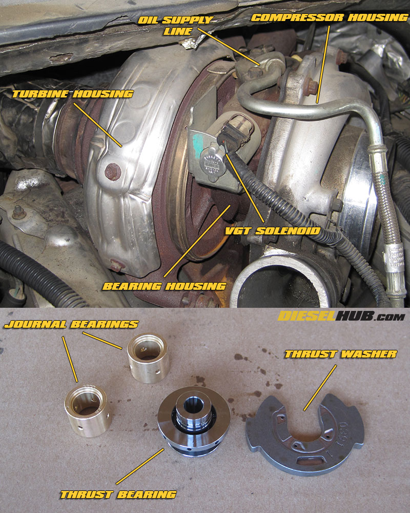
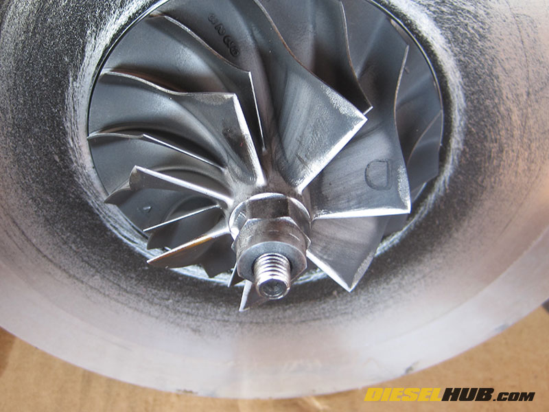
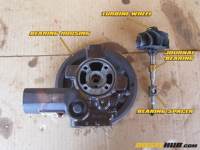
• Familiarize yourself with the components of the turbocharger; the compressor housing (air side), center cartridge (AKA bearing cartridge, bearing housing, center housing), and turbine housing (exhaust side) are the three main pieces of the turbocharger assembly.
• Remove the turbine housing heat shield (8 mm socket) and VGT solenoid (8 mm 12 pt socket). Once the VGT bracket is removed, the VGT solenoid pulls straight out (it's a tight fit as the solenoid contains a series of o-rings).
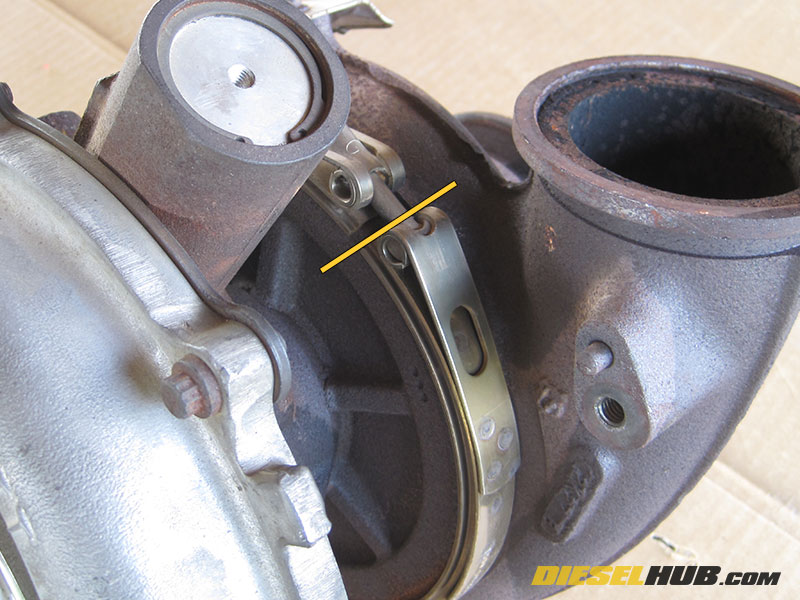
• Use a scribe or marker to index the location of the clamp that holds the turbine housing to the turbine backing plate - you'll want to reinstall the clamp in the exact same location during reassembly.
• Completely remove the nut (11 mm socket) from the turbine housing band clamp, then position the clamp upwards towards the compressor backing plate so that the turbine housing can be removed.
• Lubricate the groove between the turbine housing and bearing housing with a generous amount of penetrating lubricant (PB Blaster, WD-40, etc), then allow it to soak for a minimum of several minutes before continuing.
• Position the turbocharger vertically such that the turbine outlet (which exits to the downpipe) if face-down on the workbench.
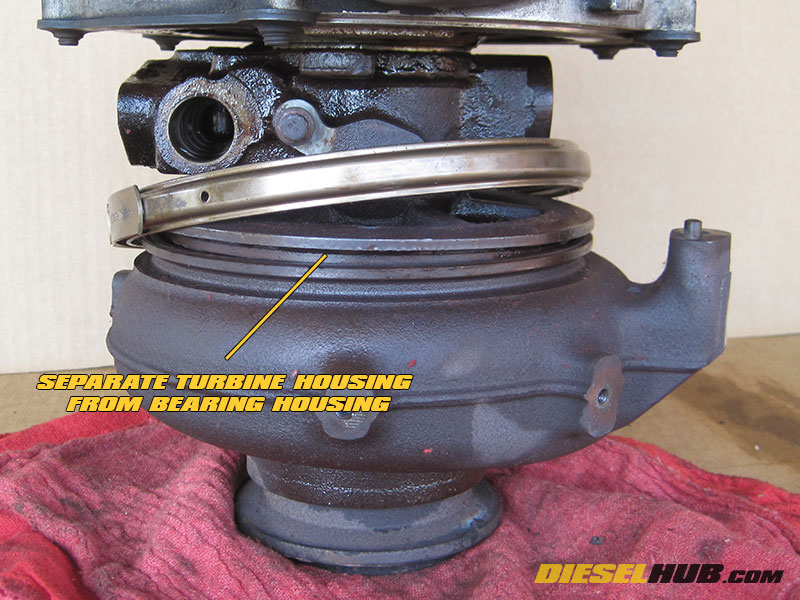
• Separate the turbine housing from the center cartridge. Our preferred method of doing this is by tipping the turbocharger roughly 30 degrees to one side, then tapping downwards on the turbine housing with a dead blow hammer - do not use a metal hammer.
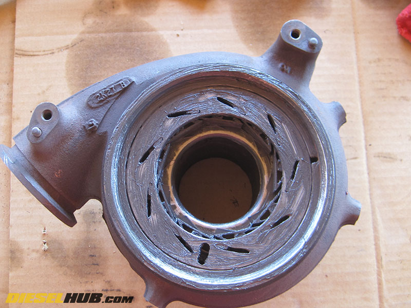
• Continue to tap 360 degrees around the turbine housing, rotating the turbocharger as you progress. You should notice the turbine housing separating from the rest of the assembly. Some turbochargers are more stubborn than others, so be patient.
• Once the groove has opened up, you can complete the separation process using a pry bar or large screwdriver, but be carefully not to mare the mating surfaces. The end goal is to have the turbocharger vertical when the housing separates so that the unison ring and vanes do not fall out (if they do fall, don't panic; we'll show you how to reassemble the turbo from scratch).

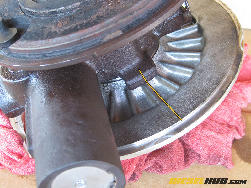
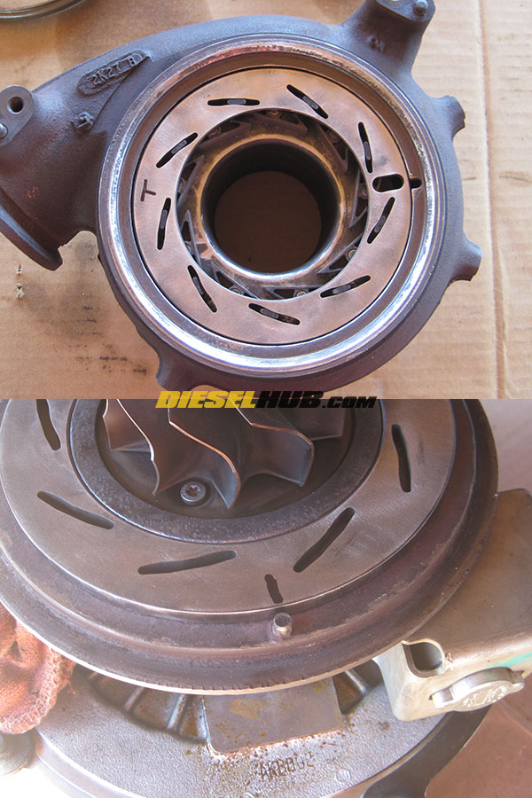
• Index the unison ring so that it can be reinstalled in the correct position. To do so, mark the turbine housing at the unison ring slot with a scribe or marker. If you lose your reference line later or accidentally skip this step, we'll show you how to find the correct position.
• Remove the unison ring and individual VG vanes. Soak the vanes in penetrating lubricant for several minutes to help break loose any hard debris.
• Index the position of compressor housing with respect to the compressor backing plate by scribing or otherwise marking a reference line such that the housing can be reinstalled in the same position during reassembly.
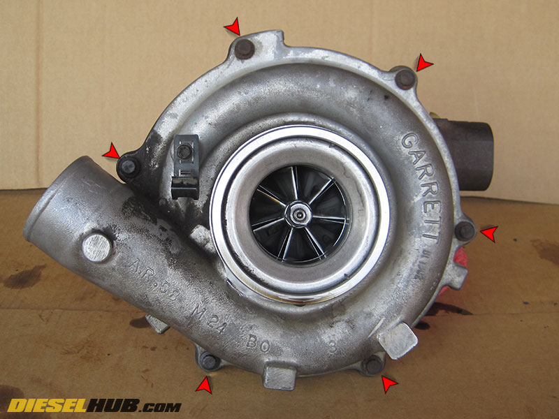
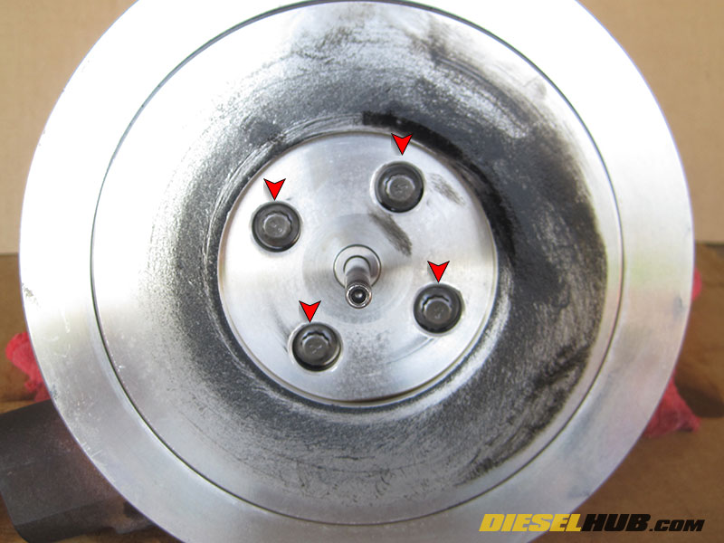
• Remove the compressor housing from the compressor backing plate by removing the series of (6) bolts around the circumference of the housing with an 8 mm 12 pt socket. With the bolts removed, CAREFULLY separate the housing from the backing plate without catching the compressor wheel.
• Now that both the turbine and compressor wheels are vulnerable, lay a series of shop towels beneath the turbine wheel, allowing the weight of the assembly to gently rest on the turbine, not the compressor.
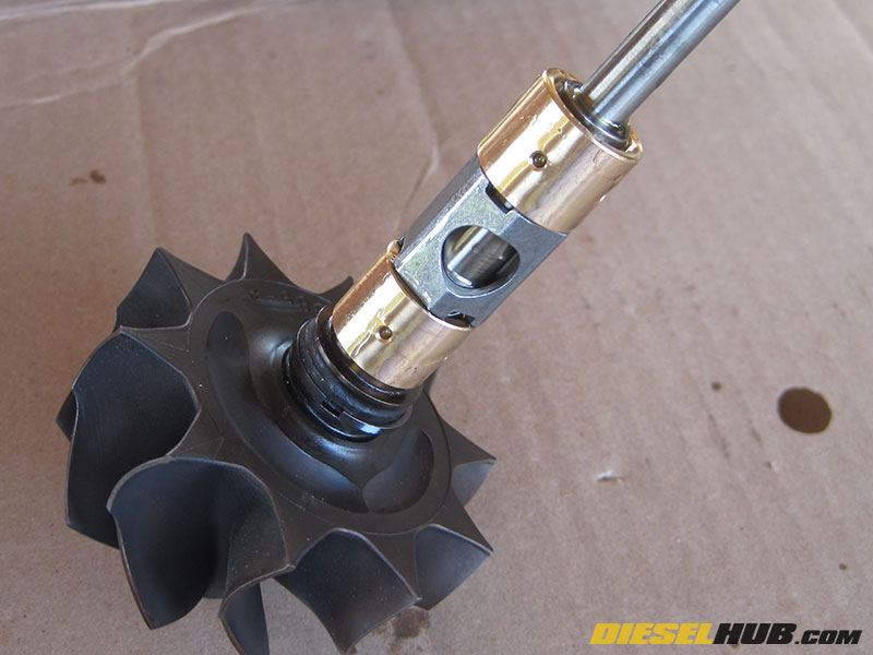
• Remove the compressor wheel from the shaft using a pair of wrenches, or by sticking the tip of turbine wheel in a vice. The turbine wheel has a semi-hexagonal head that can be held with a wrench. The size of the wrench may vary turbo-to-turbo, so find the size that fits best. A 3/4" wrench fit snugly on our turbine shaft and a 9/16" wrench/socket was the best fit for our compressor shaft; but again you may find that a different size is necessary for your turbo. The compressor wheel is threaded with a L/H thread, therefore you must rotate the wheel CLOCKWISE to loosen.
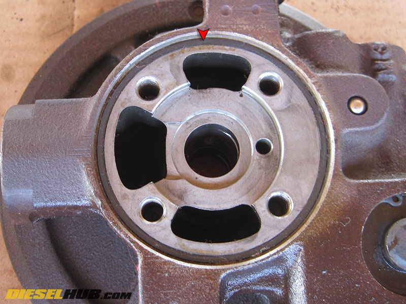
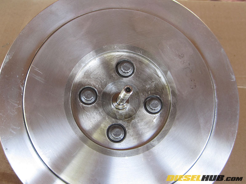
• Create a reference line between the compressor backing plate and bearing housing (see image) in order to index the parts for proper reassembly.
• Remove the (4) bolts securing the compressor backing plate to the bearing housing (8 mm 12 pt socket), then carefully separate the backing plate from the bearing housing without dragging the backing plate on the shaft.
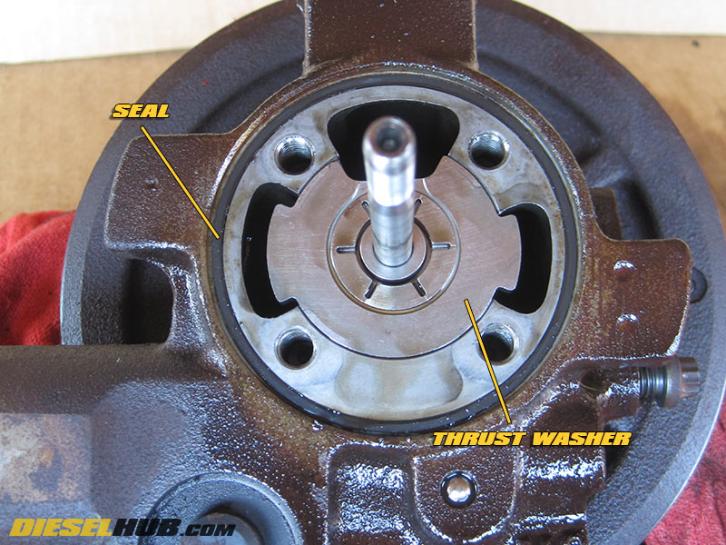
• Remove the o-ring gasket that seals the compressor backing plate to the bearing housing. Remove the thrust collar and thrust bearing (the thrust bearing may have stuck to the backing plate). Both are being replaced and can therefore be discarded.
• Position the turbocharger assembly on its side and gently tap the shaft at the compressor end with a dead blow hammer. Once the sealing ring at the turbine side is disengaged, the shaft will slide out with ease. Be careful not to drag the shaft. Do NOT hit the shaft with too much force; it should only take a few very light taps before it can be pulled out by hand. During this process, use caution to ensure the turbine wheel does not become damaged.
• Remove and discard the (2) journal bearings and spacer that come out with the shaft; do not reuse these items. If the bearings do not come out with the shaft, carefully remove them from the bearing housing.
• Thoroughly clean the turbine housing, VG vane pins, unison ring, and center cartridge. For a more in-depth guide to cleaning the VGT assembly, see: 6.0L Power Stroke VGT cleaning guide.
• Thoroughly clean the compressor housing and backing plate. Remove all oil, dirt, and debris with a mild solvent. If desired, an ultra-sonic cleaner can be used to clean the compressor wheel. Do NOT clean the compressor wheel by any mechanical means (i.e. scrubbing, sanding, etc) as it is a balanced component!

• Remove the oil seal ring from the shaft (near the inner side of the turbine wheel); a small pick set/flathead screwdriver works well, but be carefully not to mare or scratch the shaft.
• Thoroughly clean the shaft near the turbine where the oil seal ring was removed of any oil and/or deposits. Do not use harsh abrasives - a Scotch Brite pad (3M part # 07480) works well. Do not use power tools, clean by hand.
• Coat new oil seal ring with motor oil, then install. Set the shaft assembly aside in a clean location.
• Coat the new thrust bearing and thrust bearing oil seal ring in motor oil, then install the seal onto the thrust bearing. In a clean container, soak the new journal bearings, journal bearing spacer, thrust washer, and thrust bearing in clean motor oil.
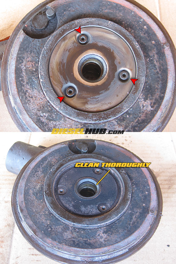
• Remove the center cover plate from the turbine side of the bearing housing (3 x T20 Torx bolts). Clean any debris and carbon build up in this location then reinstall the cover plate using the new hardware included in the rebuild kit. Do not use sandpaper, power tools, or harsh abrasives. The recommended cleaning method is using a Scotch Brite pad (3M part # 07480) by hand.
• The VGT system has two seals that need to be replaced, the first of which seals the variable geometry piston/plunger bore. Remove the internal snap ring, followed by the cover plate. The cover plate will accept the VGT solenoid bracket bolt, which can be used to pull the cover off.
• Remove the old o-ring with a pick. Coat the new o-ring with clean motor oil, then install it. After replacing the seal, reinstall the cover plate and snap ring. Do not over-insert the cover plate into the bore. The Garrett rebuild kit includes a new snap ring in addition to a new o-ring seal.

• The second o-ring seal that needs to be replaced is behind the cover plate for the gearset that controls the unison ring control pin. Remove the internal snap ring, then pull the cover straight out.
• Remove the old o-ring with a pick. Coat the new o-ring with clean motor oil, then install it. After replacing the seal, reinstall the cover plate and snap ring. Do not over-insert the cover plate into the bore. The Garrett rebuild kit includes a new snap ring in addition to a new o-ring seal.
• Thoroughly clean the center cartridge and any remaining components that have not yet been cleaned. Prepare a CLEAN workspace for reassembly. You'll want to be cautious of rag fibers in oil passages, damage to the turbine and/or compressor wheel, and debris infiltration while reassembling the turbocharger.
• Install the new compressor backing plate seal/o-ring after coating with clean motor oil.
• Remove the journal bearings and bearing spacer from the oil bath, then install onto the shaft (journal bearing first, then spacer, then second bearing journal - the components are symmetrical and therefore their orientation on the shaft is universal).
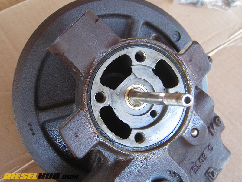
• Insert the shaft into the bearing housing, ensuring that it is installed straight into its bore as not to scratch or mare the bearing surfaces.
• With the shaft fully inserted, the turbine oil seal ring needs to be snapped into place. With the shaft oriented vertically and the end of the turbine wheel flat against a solid surface, push down on the bearing housing. When the oil ring seats, you should hear it "pop" into place and the shaft should travel into the housing an additional 1/16 to 1/8 of an inch. This also secures the shaft in the bearing housing; therefore, if the shaft easily slides out of the bearing housing, the seal has not been properly seated.
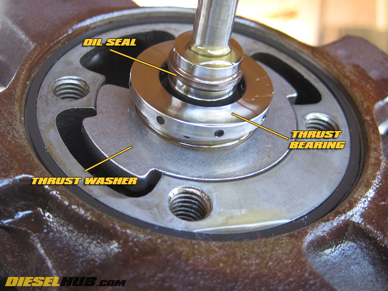
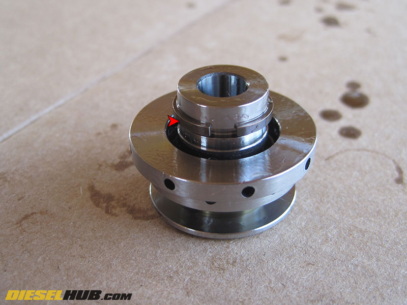
• Remove the thrust washer and thrust bearing from the oil bath. Slide the thrust washer into the thrust bearing, minding its orientation (see image for reference). The thrust washer must be installed with the grooved side facing into the center cartridge and the smooth side facing the compressor backing plate. Slide the assembly onto the shaft and position the thrust washer. The thrust washer will only fit into the grooves of the center cartridge one way.
• Use your reference marks to ensure that the compressor backing plate and bearing housings are lined up in the same position as they were removed, then Install the compressor backing plate. Push down and make sure the thrust bearing oil seal ring "pops" into place and seats completely to the backing plate (similar to seating the oil ring on the turbine side). The seating of this ring is not nearly as harsh as on the turbine side, and it is therefore unlikely you will hear it seat.
• The rebuild kit includes new backing plate hardware, so do not reuse the old bolts. Torque bolts in a cross pattern to 144 in-lbs (12 ft-lbs) with an 8 mm, 12 pt socket.
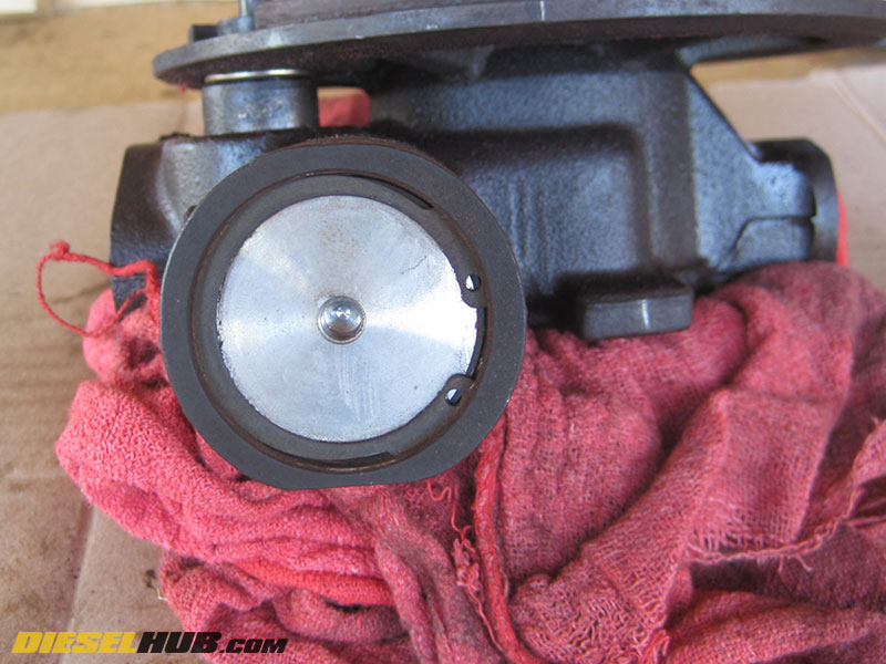
• Check the condition of the o-ring seal between the compressor housing and compressor backing plate - this is not included with the rebuild kit and will need to be purchased separately if it is damaged. If the seal appears in tact and in good usable condition, coat it with fresh motor oil.
• Reinstall the compressor wheel onto the shaft and torque to 120 in-lbs (10 ft-lbs). Recall that the shaft is L/H thread and therefore you will need to tighten counter-clockwise.
• Install the compressor housing to the compressor backing plate, using your reference mark to orient the housing in the same position as it was removed. Snug up the mounting bolts in a cross pattern, then torque to 144 in-lbs (12 ft-lbs) in a cross pattern. While tightening the bolts, continuously check that the compressor wheel moves freely. If it binds, there is a problem and/or the compressor housing is not seated evenly.
• Install the VG vanes, lightly coating the pivot pins and friction surfaces with high temperature anti-seize (Motorcraft XL-2 is spec'd to 2,400° F).
Note - if you failed to index the unison ring or your reference line was accidentally removed during cleaning, see step below before installing unison ring
• Lightly coat unison ring friction surfaces with high temperature anti-seize, then install the unison ring, seating each individual vane into its slot. Use your reference line to properly position the unison ring within the turbine housing.
Note - the unison ring and vanes only fit in one direction, so it's impossible to reverse them.
If you failed to index the position of the unison ring with respect to the turbine housing, or your reference mark was accidentally removed while cleaning the ring, the following procedures will help you position the unison ring in the turbine housing correctly:
1) Install the unison ring onto the vanes in the turbine housing, verifying it is correctly positioned so that the "fingers" of each individual vane will fit into the individual slots of the unison ring. Mark the surface of the unison ring facing you (we marked "T" for top).
2) Remove the unison ring from the turbine housing and place it against the bearing housing, aligning the VG actuating pin in the corresponding slot on the unison ring. The mark made in the previous step should be pointing against the surface of the bearing housing, i.e. it should not be visible.
3) Move the variable geometry actuator to the center position (centered between the left and right positions), then mark the location of the protruding alignment pin in the bearing housing onto the unison ring (see picture for reference).
4) Reinstall the unison ring onto the turbine housing, lining up the location of the alignment pin in the bearing housing (the mark made in the previous step) with the corresponding alignment notch in the turbine housing. The unison ring is now properly oriented and the VG vanes can be seated.

• Coat the seating/mating surfaces of the turbine housing with high temperature anti-seize.
• With the T-bolt nut removed, install the turbine housing clamp onto the bearing housing, pushing it above the flange so that it does not interfere with installation of the turbine housing.
• Carefully install the turbine housing. You must make sure that the turbine housing is installed evenly 360 degrees around the turbo, that it does not contact the turbine wheel, that the alignment pin on the bearing housing seats within the alignment notch in the turbine housing, and that the unison ring control arm pin is positioned properly within the unison ring slot.
• Once you have the turbine housing properly and evenly lined up with the bearing housing, gently tap around the perimeter of the turbine housing to seat. Following a series of taps, spin the compressor wheel and check for interference. If the compressor wheel won't spin freely, the turbine housing is seating crooked and contacting the turbine wheel - back the turbine housing off and start again. It may take a few attempts to get the turbine housing seated without contacting the turbine wheel. Continuously check that the compressor/turbine wheels spin freely while seating the turbine housing.
• Eventually, you may need to increase the force of your taps in order to fully seat the housing. Continue tapping 360 degrees around the perimeter of the turbine or bearing housing. Once the housing is fully seated, move the clamp over the flange, position it using your reference line, install the nut, then snug up the clamp so that it does not move. Verify that there is no turbine wheel interference before continuing.
• Torque the turbine-to-bearing housing clamp to 160 in-lbs, then loosen the T-bolt nut and torque to 50 in-lbs. Tap the perimeter of the turbine housing with a dead blow hammer several times, then torque the clamp to 150 in-lbs.
• Reinstall the VGT solenoid after soaking the tip of the solenoid and o-rings in clean motor oil. Coat the collar bracket bolt with high temperature anti-seize.
• Verify compressor/turbine wheel clearance by pushing downwards on the compressor wheel/shaft while rotating it - if the compressor and/or turbine wheel contacts the housing, there is a problem. Repeat this test at various angles. If neither the compressor wheel nor the turbine wheel contacts the housing, reinstall the turbocharger (see 6.0L Power Stroke turbocharger reinstallation procedures for support).