GM 6.5 Diesel Glow Plug System
A glow plug is little more than a large resistor; when electrical current is applied across the resistive element (tip), it rapidly heats. The term "glow plug" is derived from the fact that the tip will literally glow red as it generates heat. The purpose of a glow plug is to supply heat within the combustion chamber and facilitate fuel ignition during engine starting. The total heat generated in the combustion chamber as a result of compression is relative to intake air charge temperature, engine temperature, and cranking speed; peak engine speed during starting is significantly lower than normal engine idle speed and heat generated as air is compressed is rapidly absorbed by its surroundings when an engine when it is "cold". Glow plug systems act as a starting aid to ensure that an adequate air temperature is achieved so that autoignition can occur when fuel is injected into the air charge.
Starting fluids, including those marketed as safe for diesel engines, should never be used in any GM 6.2L or 6.5L engine. The combustion of starting fluids is uncontrollable in compression ignition engines and glow plugs are likely to ignite starting fluids spontaneously; severe engine damage is likely. For information on the compatibility, risks, and consequences of using starting fluids in diesel engines, see: Using Starting Fluid in Diesel Engines.
Basic Operation
The glow plug system has two simple cycles, pre-heat and post-heat. The pre-heat cycle occurs when the ignition switch is placed in the "run" position and the wait-to-start or glow plug pre-heat lamp is illuminated in the instrument cluster. During this brief period, the glow plug controller activates the glow plug relay and power from the vehicle batteries is distributed to each individual glow plug. After the glow plugs have heated for a predetermined period of time, the glow plug controller deactivates the glow plug relay and thus power flow to the glow plugs. At this time, the wait-to-start/glow plug light in the instrument cluster is deactivated, instructing the operator that the engine is ready to start.
Under certain conditions, specifically in cooler ambient temperatures and low engine coolant temperatures, a post-heating cycle will be initiated during engine cranking and/or immediately after the engine is started. When commanded by the glow plug controller, the glow plug relay will be activated in one to several short (1 to 2 second) bursts. Note that the wait-to-start/glow plug light will illuminate anytime the glow plug relay is activated. The purpose of the post-heating process is to maintain complete combustion and reduce emissions during and immediately after engine starting.
With the exception of the early GM 6.2L diesels (1982 - 1984), all 6.2L and 6.5L diesels employ a combination glow plug controller/relay. This assembly is serviced as one unit, as the relay cannot be separated from the controller and visa versa. Additional information on these glow plug controllers is available here: GM 6.2/6.5 Diesel Glow Plug Controller Replacement.
Glow Plug System Diagnostics
Note that block heater usage is recommended on all 6.2 and 6.5 diesels being stored in ambient temperatures below 32° F. The concern is not necessarily that the engine will fail to start in these cool temperatures, but it is likely to be difficult with lengthy cranking times and the risk of excessive fuel dilution during initial engine warm up is relatively high. Thus, using the engine block heater for several hours before starting will provide various benefits and protect your engine in such extreme conditions.
It would be exceptionally rare for all 8 glow plugs to fail simultaneously, but we high recommend replacing all 8 plugs at the same time. If a single glow plug fails, the likelihood that glow plugs in subsequent cylinders are near the end of their service life is high. Additionally, their is a moderate risk of glow plug tips swelling (additional information on the subject is provided below), becoming stuck, or even breaking off and dropping into the combustion chamber so we highly recommend replacing glow plugs as a standard service procedure rather than waiting for one or more to fail.
For more comprehensive information on glow plug system diagnostics, or if the tests below are unable to identify your problem, see: GM 6.2 and 6.5 Diesel Glow Plug Diagnostics and Troubleshooting.
Visual Inspections
In the event an engine will not start and the glow plug system is suspected, consider the following visual inspections as a reasonable starting point:
- Inspect for loose and/or corroded connections and terminals at the glow plug controller (replace controller if present).
- Inspect for pitting and/or melted plastic around the terminals on the glow plug controller (replace controller if present).
- Inspect the fuse for the glow plug controller (refer to owners manual for fuse position).
- Inspect the glow plug harness, wires, and connectors; replace or repair segments that are damaged, burned, melted, or otherwise compromised.
- Inspect for smoke emitted from the tailpipe while cranking. White smoke indicates raw fuel (no combustion) and black or charcoal colored smoke indicates partially burned fuel; a glow plug system fault is a likely culprit in both instances if there is a hard start/long crank or no start condition. No smoke while cranking could indicate a fuel system as it may indicate that the engine is not getting fuel or a related problem is prohibiting the engine from starting.
Additionally, listen for relay "chatter", a prominent clicking sound indicating that the glow plug relay is being rapidly activated and deactivated (switching between "on" and "off" states rapidly). This condition is typically indicative of a faulty or glow plug controller. If engine cranking speed seems to be slow, verify battery voltage; a slow cranking engine is not going to start in extremely cold conditions, even with a fully functional glow plug system.
Glow Plug Controller Test
Testing the glow plug controller is as simple as confirming the output current of the relay with an inductive ammeter (recommend Klein CL800). Place either negative battery cable inside the test hoop of the ammeter and measure the current draw through the battery cable during the pre-heat cycle (wait-to-start/glow plug light illuminated in instrument cluster). 40 to 50 amps (nominally, and with a reasonable margin of variance) would indicate that the glow plug relay is activating and each glow plug is drawing the 6 to 10 amps of current that it should. A low current draw would indicate that battery voltage is not reaching all or any of the glow plugs.
If current draw is low or non-existent, check for battery voltage at the glow plug controller (large lug, red wire). If there is no voltage between this lug and either battery ground, the primarily wire supplying power to the controller is disconnected or there is a blown fusible link. If there is adequate input voltage but now output voltage (check voltage at opposing lug on the controller with wait-to-start/glow plug light illuminated), the controller has failed and likely needs to be replaced.
Glow Plug Test
Each individual glow plug can be tested without removing it from the cylinder head. Using a digital multimeter or equivalent device, measure the resistance across the glow plug (set device to read Ohms, often indicated by the Ω symbol). This is done by touching one probe/test clip to the male spade connector at the top of the glow plug and the second probe/test clip to the base of the glow plug (or any good ground, including the engine block). A brand new ACDelco glow plug should read 0.8 Ω of resistance, however any reading between 0.8 and 1.8 Ω is considered normal for a fully functioning glow plug in good condition. If resistance values are not within this range, replace all 8 glow plugs. As glow plugs "wear", the resistance measurement increases.
Fusible Link Test
The simplest method of testing a fusible link to measure resistance across the fusible link or perform a continuity test at either side, both of which can be done quickly with a multimeter. The glow plug wiring on a 6.2 or 6.5 diesel is primarily fusible link and there are fusible links between the battery and glow plug controller. Start by testing from each individual glow plug connector to the glow plug controller, then isolate any problem areas. Fusible links must be replaced with the same gauge wire and length as removed.
Glow Plug System Parts List
Part Description |
Part Number(s) |
Remarks/Notes |
|
Glow plug |
ACDelco 60G(GM 12563554) |
[1] |
|
Glow plug controller |
1992 - 1993 models |
--- |
|
1994+ models |
|||
Glow plug connector |
[2] |
||
Glow plug harness extension |
[3] |
||
Glow plug harness extension connector (chassis side) |
[4] |
||
High temperature anti-sieze |
ACDelco 10-4039 |
[5] |
|
[1] - Recommend Genuine GM/ACDelco replacement glow plugs; many aftermarket brands have a reputation of swelling related problems in 6.2 and 6.5 diesel applications.
[2] - OEM spade connector on fusible link pigtail, includes high temperature sleeving to protect connector from exhaust manifold heat.
[3] - For 1992+ 6.5L turbodiesel, passenger side cylinder 3 and 5 glow plug connector assemblies; plug-and-play connection, no splicing.
[4] - Mating side of glow plug harness extension; repaired by splicing new connector pigtail into wiring harness.
[5] - All listed products rated to a maximum 2,400° F exposure temperature. A high temperature anti-sieze lubricant is highly recommended; apply a very light coat to glow plug threads prior to installation.
On turbodiesel models, the cylinder 4 and 6 glow plugs (passenger side) employ metal heat shields to protect against heat radiating off of the turbocharger, exhaust manifolds, and downpipe as they are located in close proximity to these components and heat is not easily dissipated. In order to aid in the serviceability of these glow plugs and remove the heat shields, the glow plug wiring harness for these cylinders use special extension wires that can be disconnected from the main harness. These extensions wires and the glow plug connectors themselves tend to become damaged or extremely brittle and are generally replaced with the glow plugs. Referred to as "glow plug harness extension" or "glow plug wire extension", we recommend replacement part glow plug harness extension RT-250701 available through our online store.
Glow plug connectors that do not fit snuggle on the glow plug terminal or have wires that are torn/deteriorated should be replaced. Do not attempt to repair the harness with standard automotive wire as a permanent fix as each connector in the harness is wired with fusible link. Replace with 6.5 diesel glow plug connector RT-250502, which also includes heat resistant sleeving to protect the connectors from exhaust manifold heat.
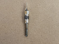
ACDelco 60G Glow Plugs
We highly recommend the OEM ACDelco 60G (GM 12563554) replacement glow plugs and, at this time, cannot recommend any alternative or aftermarket replacements that we believe live up to the quality of the Genuine GM units. Be mindful that there is an abundance of fake GM parts available across various selling platforms. These fakes are typically masked well behind factory appearing packaging. To find a fake, look for the ACDelco logo on the body of the glow plug itself; authentic ACDelco glow plugs have "ACDelco" etched into the stem of the glow plug just below the threads. The counterfeits that we're aware of lack any ACDelco markings on the physical product itself but have convincing, indistinguishable packaging.
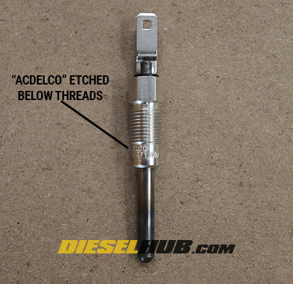
How to identify Genuine ACDelco glow plugs
6.5 Diesel Cylinder Numbers
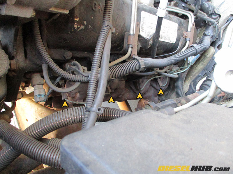
On the 6.2 and 6.5 GM diesels, cylinders 1, 3, 5, and 7 are located on the driver side of the engine while cylinders 2, 4, 6, and 8 are located on the passenger side. All passenger side glow plugs are located to the left (towards the cabin) of that cylinder's respective exhaust manifold runner. All driver side glow plugs are located to the right (towards the radiator) of that cylinder's respective exhaust manifold runner. The cylinder map below serves as a visual aid for the correct cylinder numbers, which will be referenced in the procedures below.
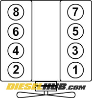
6.2 & 6.5 diesel cylinder numbers
How to Replace Glow Plugs a GM 6.2 & 6.5 Diesel
Click any thumbnail to view high resolution, fullsize image
• Disconnect both negative battery terminals and the passenger side positive battery terminal. Remove the passenger battery and battery tray.
• Remove the passenger side inner fender. You'll need a 13 mm, 10 mm, and possibly a 7 mm socket in order to remove the variety of hardware (most bolts have a 13 mm head). You may also need to remove several plastic body panel clips if there is a rubber or plastic shield attached to the inner fender. Lastly, do not forget to disconnect the clips holding the coolant hoses inside the engine bay to the passenger side inner fender.
• All glow plugs have a single spade connector attached at the top. After removing the connector, glow plugs are removed with a 10 mm deep socket.
• Lightly coat the threads of each new glow plug in high temperature anti-seize before installing. This will act as a lubricant to help prevent cross-threading as well as make future replacement less challenging. Installation of the new glow plugs is precisely reverse as installation. Glow plugs should be tightened down "snug"; do not overtighten.

• The cylinder 2 glow plug is easy to access and straight forward. Carefully remove the connector, then remove the glow plug. We used a 5 inch extension, which places your hands far enough outwards to avoid busting a knuckle.
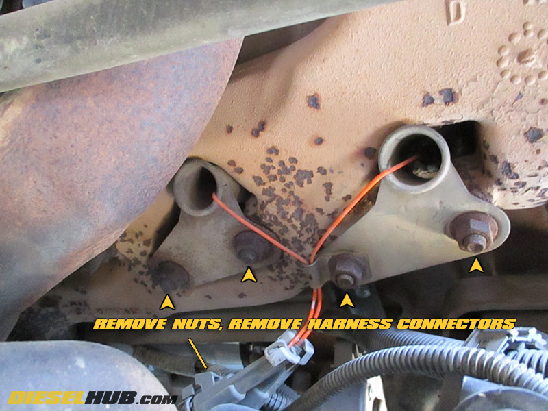
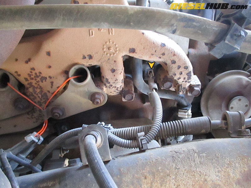
• The cylinder 4 and 6 glow plugs both have heat shields protecting the glow plug harness. They are also the only "serviceable" harnesses as the female spade connectors at the glow plug frequently become damaged during removal.
• Disconnect the harness connectors (not at the glow plug) then remove the heat shields using a 15 mm socket (refer to image for clarification).
• Do not attempt to remove the spade connector from the glow plug before removing the heat shield; it will likely break.
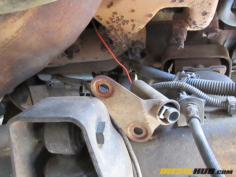
• Pull the heat shield down towards the harness extension connector, then you can reach the spade connector at the glow plug.
• Once again, we used a 5 inch extension for the cylinder 4 glow plug.
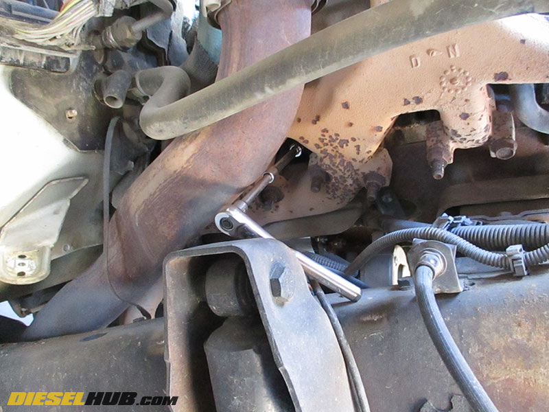
• A 5 inch extension and 1/4" drive swivel joint was used for the cylinder 6 glow plug. The turbocharger downpipe does not need to be removed to access any of the cylinders, there is ample room.
• If you break the cylinder 4 or 6 harness connector, see the information provided in the introduction above. If you don't manage to break a terminal, you're one of the lucky few; they tend to disintegrate.
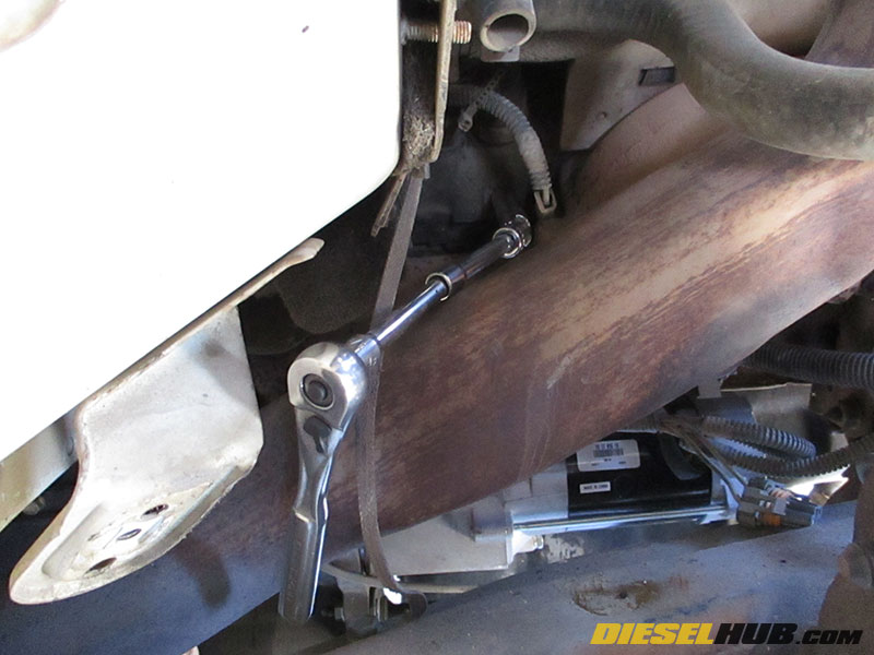
• The cylinder 8 glow plug is also accessible using a 5 inch extension and a 1/4" drive swivel joint. There's plenty of room to work around the turbocharger downpipe this way.
• Reinstall the inner fender, battery tray, etc once the passenger side glow plugs have been replaced.
• The driver side glow plugs are relatively straight forward and nothing needs to be removed to access them. A 10 mm, 1/4" drive deep socket with no extension can be used with ease.
• Once the driver side glow plugs have been replaced, reinstall the negative battery cables and test for proper glow plug operation.
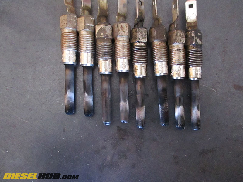
• As previously mentioned, we highly recommend OEM ACDelco 60G replacement glow plugs. Of the 8 glow plugs removed from this engine, all the original ACDelco plugs are in relatively good condition. However, if you look closely you'll notice a few of the plugs have distorted tips. Aftermarket glow plugs have a tendency to swell overtime and this is potentially harmful to your engine should one fail.
Summary & Key Points
• 6.5 diesels rely on glow plugs as a starting aid, particularly in colder weather. A faulty glow plug system can result in a no start, hard start, and/or long crank condition.
• Glow plugs are just one piece of the larger glow plug system; a glow plug controller/relay fault can disable the entire system. Isolating glow plug system problems typically requires several tests that rely on a multimeter.
• Replacing glow plugs is relatively simple and straight forward with basic hand tools, but don't forget to inspect the connectors and wiring harness when handling these components.