A faulty temperature sensor is typically indicated by one of two conditions. 1) the temperature gauge in the instrument cluster reads erratically or incorrectly. 2) the glow plug pre-heat cycle time is too short and causing a hard start condition (1994+ only). Replacing the temperature sensors is simple enough, although the engine coolant should be drained below the level of the sensors to reduce spilling while changing the sensor(s).
6.5L DIesel Coolant Temperature Part NUmbers
Part Description |
Part Number(s) |
Remarks/Notes |
Cylinder head coolant temp sensor, 1992+ models) |
[1] |
|
Coolant crossover pipe temp sensor (1994+ models) |
[2] |
[1] Temp sensor with gray electrical connector.
[2] Temp sensor with black electrical connector.
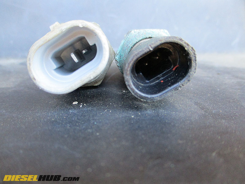
The cylinder head mounted temperature sensor found on all 6.5L GM diesels has a gray connector and is not interchangeable with the sensor mounted in the coolant crossover tube of 1994+ model year engines. This sensor has a black connector, and the pin locations on the two sensors differ such that the harness connectors will not fit into the incorrect sensor. The figure below describes the shape and pin locations of the respective connectors. Neither sensor is particularly expensive and we often replace them preventively during a cooling system service, especially when the system is well over due for a flush. Part numbers for each sensor are listed above in the introduction.

Cylinder head vs coolant crossover tube temperature sensors; note difference in connector color
6.5L Diesel Coolant Temperature Sensor Replacement Procedures
Click any thumbnail to view high resolution, fullsize image w/ details
• Disconnect both negative battery cables.
• There are one of two methods of replacing the sensor(s); be fast and don't drain the radiator, or drain the radiator to eliminate the possibility of spilling coolant.
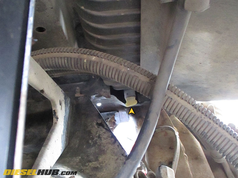
• If you choose to drain the radiator, there's a petcock/drain valve on the driver side. Many trucks have a crossmember that covers the nipple of the drain valve and makes it near impossible to attach a hose. Place a drain pan below the valve and drain the radiator. If you use a clean pan, the coolant can be reused.
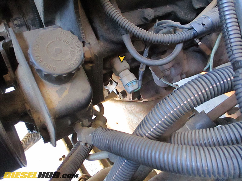
• Remove the electrical connector from the temperature sensor after releasing the safety clip.
• The temperature sensor mounted to the cylinder head is located on the driver side near the front of the engine (in front of the cylinder 2 glow plug). Remove it with a 13/16" socket and install the new sensor snug.
• The ACDelco sensors come with a thread sealant already applied and there is therefore no reason to use Teflon tape or any other sealant. Use dielectric grease on the connector terminals.
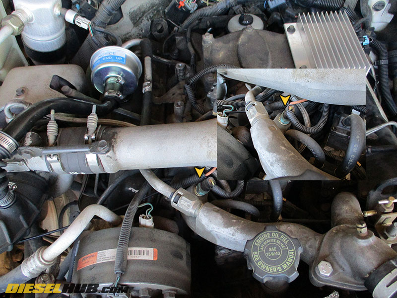
• The temperature sensor mounted on the coolant crossover pipe (1994+ model years only) is located towards the passenger side just before the upper intake manifold tube (refer to image).
• Remove the sensor with a 3/4" socket and install the new sensor snug.
• The ACDelco sensors come with a thread sealant already applied and there is therefore no reason to use Teflon tape or any other sealant. Use dielectric grease on the connector terminals.
• Reinstall the electrical connectors, refill the engine cooling system (if applicable), reconnect both negative battery cables and test for leaks.
• The image at left identifies the subtle differences between the two sensors.