6.9L and 7.3L IDI Diesel Oil Cooler Parts List
Early 83/84 model year 6.9L IDI engines may have a rare six o-ring oil cooler. Later 6.9L, all 7.3L IDI, and all 7.3L Power Stroke engines featured the standard four o-ring oil cooler design. The part numbers are applicable for all these engines, however the early 6.9L IDI will require (4) small o-rings and (2) large o-rings, while the late 6.9L and all 7.3L IDI/Power Stroke require (2) small o-rings and (2) large o-rings per oil cooler. The following parts list is applicable for all 1983 to 1994 6.9L/7.3L IDI engines, naturally aspirated and factory turbocharged.
Part Description |
Part Number(s) |
Remarks/Notes |
|
Large oil cooler o-ring |
[1] |
||
Small oil cooler o-ring |
|||
Front oil cooler header to engine block gasket |
F-Series |
Ford E3TZ-6A636-G |
[2] |
E-Series |
Ford E3TZ-6A636-C |
||
Rear oil cooler header to engine block gasket |
Ford E3TZ-6A636-H |
||
Front oil cooler header |
F-Series |
Ford E4TZ-6881-C |
[3] |
E-Series |
Ford E4TZ-6881-A |
||
Rear oil cooler header |
F-Series |
Ford E4TZ-6881-B |
|
E-Series |
Ford E4TZ-6881-D |
||
Complete oil cooler assembly |
Ford F3TZ-6A642-C |
--- |
|
[1] Sold individually. (2) small and (2) large o-rings required for late 6.9L IDI and all 7.3L IDI engines. Early 6.9L IDI engines may require (4) small o-rings and (2) large o-rings.
[2] Fel-Pro gasket set services F-Series and E-Series, front and rear headers.
[3] Oil cooler headers are becoming obsolete and primarily available through obsolete part dealers in the form of NOS replacements. Headers only require replacement if they are cracked or otherwise damaged at the sealing surfaces.
6.9L and 7.3L IDI Oil Cooler Removal and Rebuild Procedures
Click any thumbnail to view fullsize, detailed image

• The oil cooler is longitudinally mounted on the driver's side of the engine, just below and parallel to the exhaust manifold.
• Disconnect both negative battery cables.
• Drain the engine oil and remove the oil filter. Leave the oil pan drain plug off until the oil cooler has been replaced.
• Drain the engine coolant as much as possible. Save the coolant in clean plastic containers so that it may be re-used, unless it is old and time to replace.

• The oil cooler consists of a heat exchanger (long cylindrical tube) with caps at each end called headers. Each header is sealed to the cooler tube by a pair of o-rings (4 o-rings total per oil cooler).
• This oil cooler is not mixing oil and coolant, but has a developed a severe leak at both ends and is therefore losing oil rapidly. If you're waking up to a mysterious oil stain in your driveway, check the oil cooler for leaks at both headers with the engine is running.
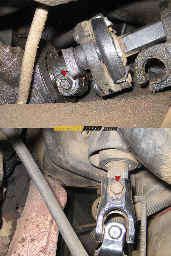
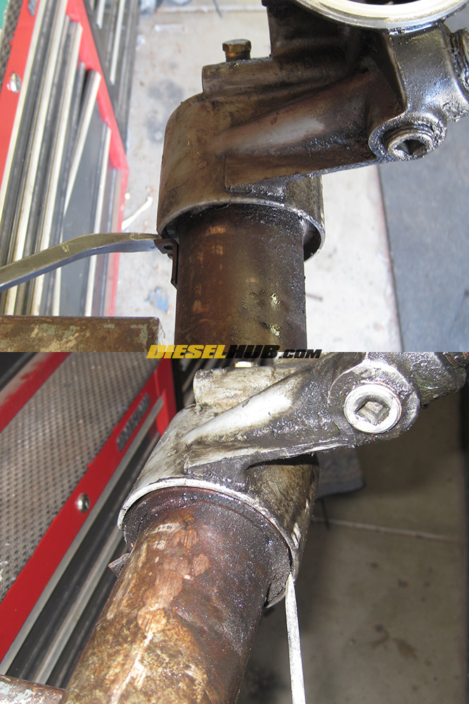
• Rotate the steering wheel until the lower steering shaft bolt is accessible (at the steering box). Loosen the bolt with a 10mm socket (a long extension is necessary), then slide the shaft towards the firewall and off of the steering box input shaft.
• Rotate the steering wheel until the upper steering shaft bolt is accessible, then remove it with a 13mm socket. Separate the steering shaft from the steering column and completely remove it from the vehicle.
Note - the steering shaft must be removed at the steering box first.
• Extract as much fluid as possible from the power steering pump fluid reservoir. This will reduce spillage when the pump is removed.
• Position an oil drain pan below the power steering pump.
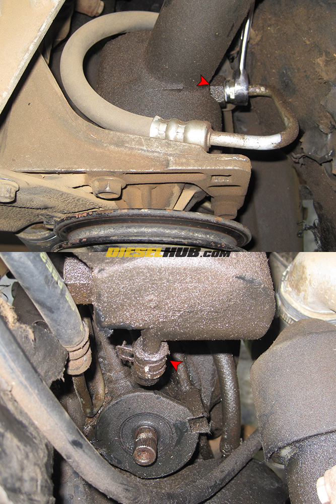
• Remove the high pressure hose (driver side of the pump) from the power steering pump using a 11/16" wrench (flare nut wrench recommended to avoid stripping the fitting nut). Cap the hose with a piece of a clean shop towel or similar method.
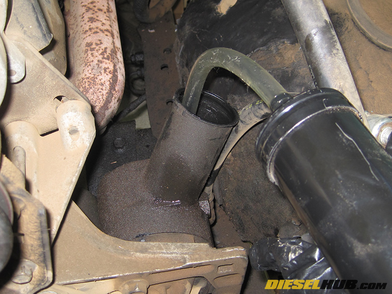
• Remove the low pressure/return hose from the bottom of the power steering pump (held on by a hose clamp). Cap the nipple and hose as to reduce fluid loss while the pump is being removed.
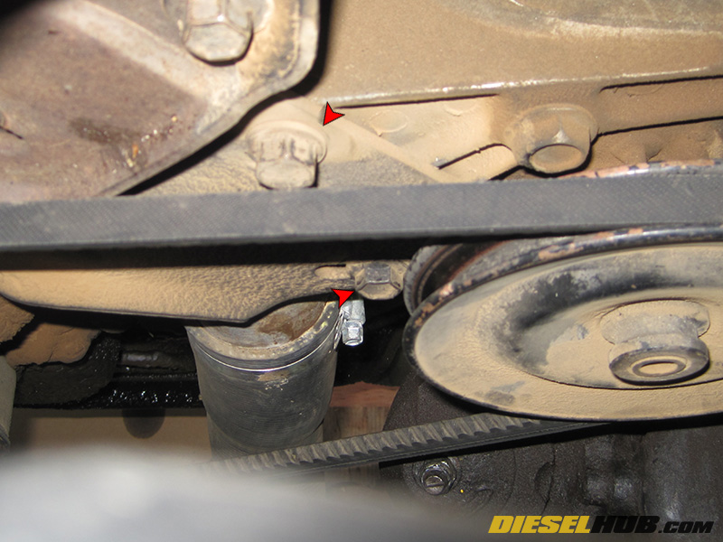
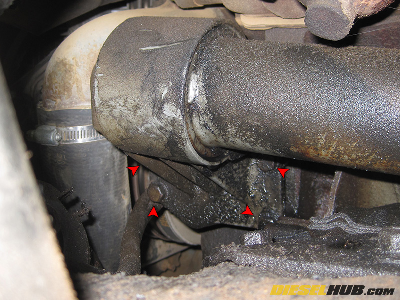
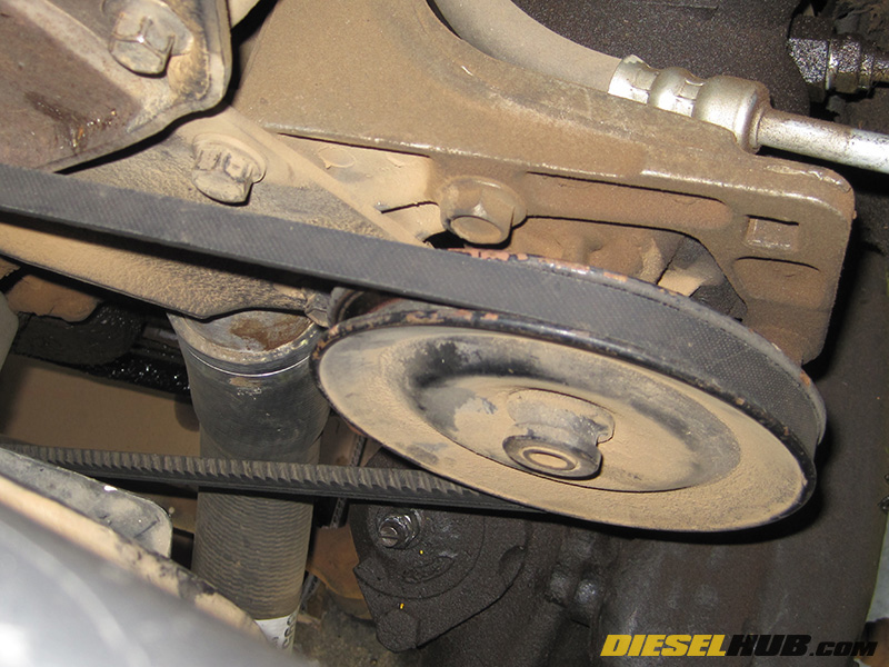
• Loosen the bolts on the power steering pump bracket (marked with red arrows in fullsize image) then release tension and remove the belt. The lower bolt (slotted portion of the bracket) requires a 14mm socket while the upper bolt requires a 16mm socket.
• Completely remove the 14mm and 16mm power steering pump bracket bolts, then remove the power steering pump and set aside.
• Removing the power steering pump greatly improves access to the oil cooler and will allow for the cooler to be rotated in a manner that it can be removed without needing to lift the engine or take apart the cooler from under the hood.
• Remove the four front oil cooler header bolts, all of which require a 9/16" socket (an extension will be required to reach most of the bolts). You may choose to remove the ground cable on the driver side of the engine block, which will improve accessibility but is not required. All four front header bolts are the same size and length.
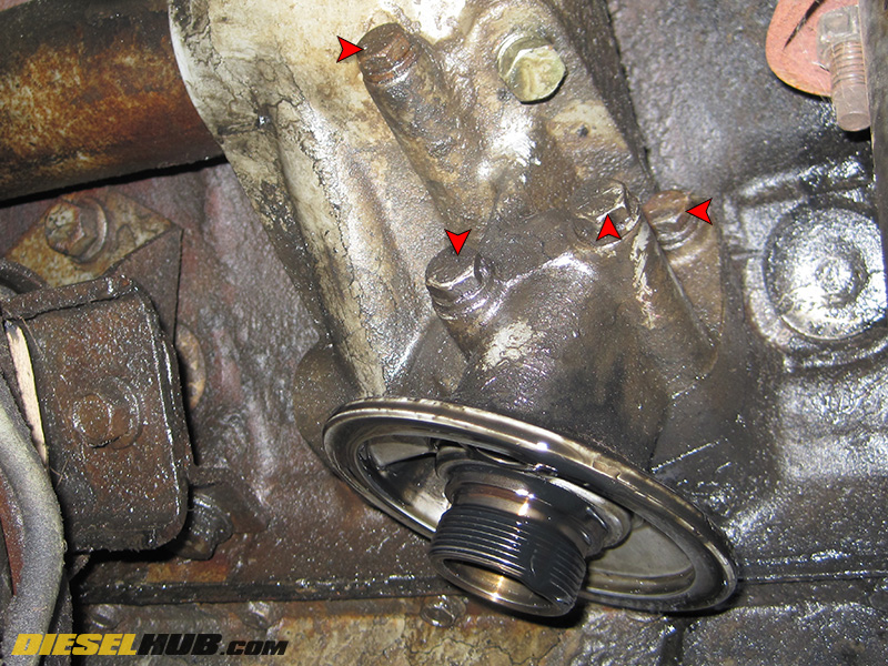
• Remove the four rear oil cooler header bolts, all of which require a 1/2" socket (various extension lengths may be necessary to reach the bolts). The rear header bolts are varying lengths - label the bolts as they are removed, or refer to the diagram below for proper assignment of the bolts.
• Unless you're a contortionist, you'll want a second person to help you guide the oil cooler out. First, you'll need to gently tug the oil cooler off the engine block. Have someone guide the front oil cooler header from under the hood while another directs the rear oil cooler header from underneath the truck.
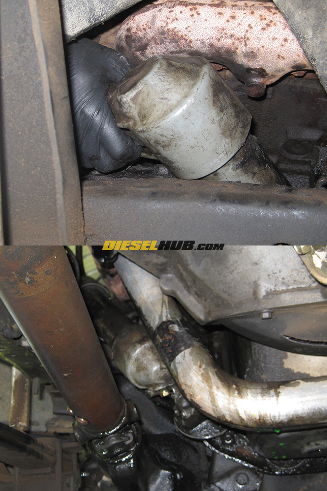
• We'll be removing the oil cooler from underneath the truck, so begin by directing the rear of the cooler downwards. For four wheel drive pickups, stay between the drive shaft and engine/bellhousing.
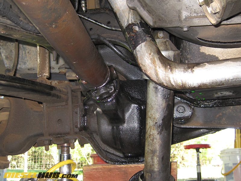
• You will need to rotate the oil cooler as you travel downwards so that the filter housing can pass between the engine and exhaust. If you're having difficulty, communicate with your helping hand in order to find the correct angles. The process is difficult to explain in words, but refer to our pictures if you're having trouble getting the proper angles to slide the cooler out.
Note - this is why removing the power steering pump is necessary, as you can not rock the front of the oil cooler upwards with the pump installed.
• Once you've removed the oil cooler from the vehicle, tip the cooler over a drain pan and drain as much oil out of it as possible.
• Carefully clamp the oil cooler in a vice - do not overtighten! Only clamp it tight enough to hold it in place or damage may occur to the heat exchanger (which is particularly expensive to replace).
• Pry the front and rear oil cooler headers off - there are tabs at either end that can be used to pry on. Once the first o-ring land is exposed, you can use a flathead screwdriver to gently pry it the rest of the way off.. If you bend the tabs, which is likely, simply bend them back.
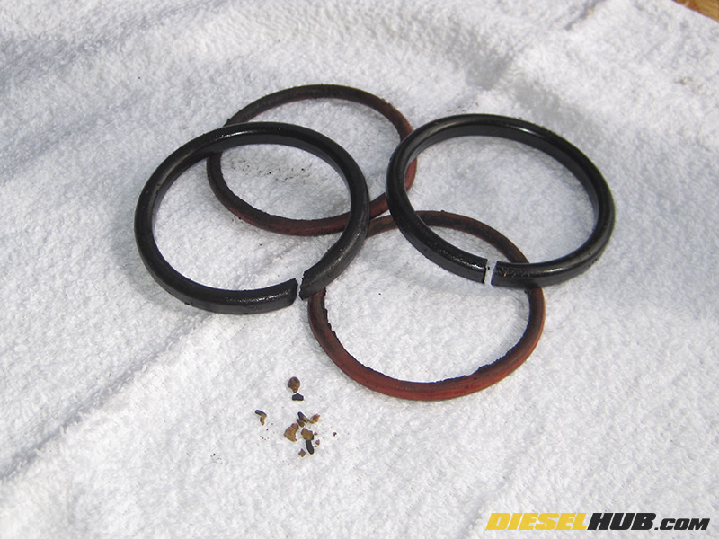
• Remove the o-rings from each end of the oil cooler heat exchanger. They will likely be hard, brittle, disfigured, and possibly broken. In our case, both of the large o-rings had cracked after becoming rock solid, thus our severe oil leak.
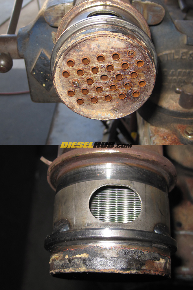
• Clean and prep the oil cooler for new o-rings - begin by cleaning any debris from the heat exchanger tubes. A piece of solid core copper wire or plastic weed eater line both work well for removing solid debris; follow with a shot of brake cleaner or similar cleaning agent through each tube.
• Next, remove any rust, grime, and remnants of the oil o-rings from the oil cooler sealing surfaces (including the interior of the headers and the gasket mating surfaces). A fine wire brush works well, but avoid using any coarse abrasives as you do not want to mar the machined surfaces where the o-rings seat.
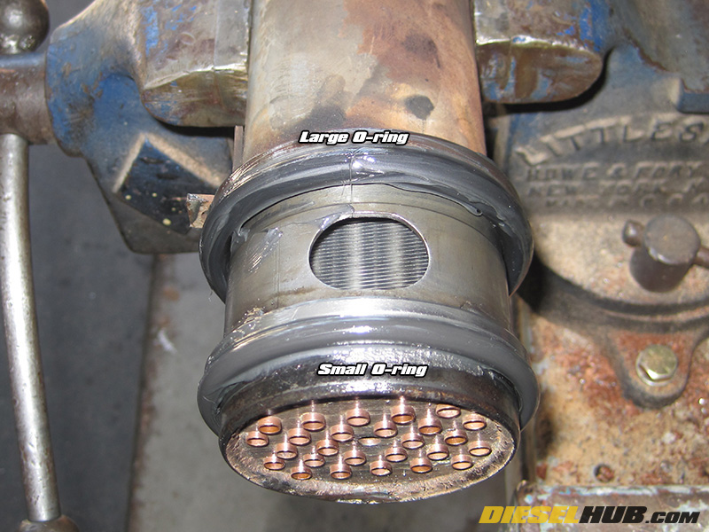
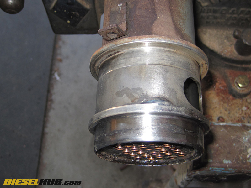
• Liberally coat the large o-rings (furthest inset) with grease, then install them in place.
• Liberally coat the small o-rings (closest inset) with grease, then install them in place.
Note - The o-rings are identical for the front and rear oil cooler headers; each requires 1 large and 1 small o-ring. The large o-ring must be installed first. See fullsize image for detailed view.
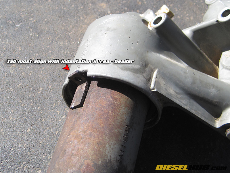
• Once the o-rings have been installed, you'll need to press the headers back on. The rear header has an indentation in which the tab on the heat exchanger must insert into. The front header does not have a tab and is free to spin on the heat exchanger once installed, so its orientation is not important.
• Installing and seating the headers can be extremely difficult. We recommend using a large press. If you do not have access to a press, you can get creative with a floor jack, porta-power, etc.
• The caps should require some force to seat over the o-rings (you generally can't install them by hand), but use discretion as not to apply too much force - often times, the header and heat exchanger seat crooked and bind. If this is occurring, try deburring both surfaces until the header slides on smooth with only moderate pressure.
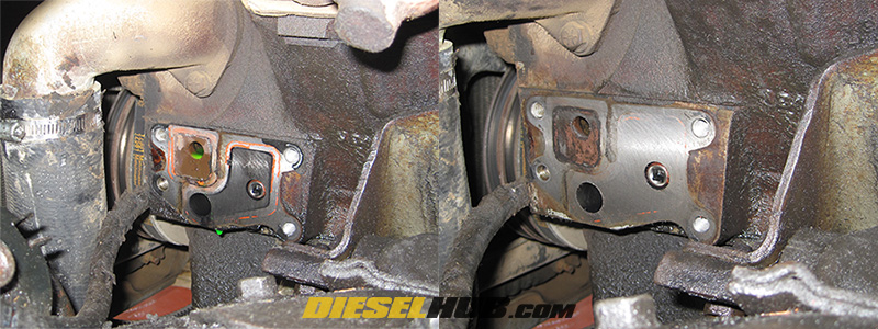
• Once the oil cooler has been rebuilt and/or replaced, clean the mating surfaces on the engine block until the machined surfaces are dry, smooth, and free of any debris, gasket material, silicon, etc.

• While cleaning, use small pieces of a clean rag to keep debris from entering the oil and/or coolant passages.
• Line both oil cooler headers with a very small bead of silicon, install the gaskets, and apply another small bead of silicon to the block side of the gasket. You should be using a high temp RTV silicon - Ford's TA-31 RTV silicon is highly recommended.
• Carefully maneuver the oil cooler back into place and install it (again with two people to avoid bumping the gaskets). Install all bolts snug. After the silicon has set (if applicable, see product directions), torque the front header bolts to 24 lb-ft and the rear header bolts to 14 lb-ft in a cross tightening fashion.
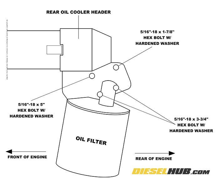
• For reference, see diagram at left for location of various bolt lengths for the rear oil cooler header. The front header bolts are all the same length and are interchangeable.
• Install the oil drain plug, a new oil filter, and verify that the radiator petcock is closed. Fill the crankcase with fresh engine oil and the radiator with coolant/distilled water in a 50/50 ratio. Don't forget to check and adjust the DCA/SCA level after a few drive cycles.
• Reinstall the steering pump, connect and tighten the steering pump low/high pressure hoses, and fill the fluid reservoir to the cold fill line.
• Prime the power steering pump by operating the pulley clockwise by hand. Fill the fluid reservoir with power steering fluid as the level decreases. Once the system is done purging air and the fluid level remains constant while the pulley is being rotated, double check the fluid level is at the cold fill indication mark on the dipstick and then replace the cap.
• Install and tension the power steering pump belt. Reinstall the steering shaft. Apply high strength thread-locker on the upper steering shaft bolt.
• Check the engine oil and verify that there is no water in the crankcase. If there is visible water mixed with the engine oil, the oil cooler is not sealed properly.
• Check for oil and coolant leaks around the sealing edges of the oil cooler headers.
• Prime the engine oil and coolant systems by turning the engine over with the ignition in the off position. This is done with the keys out of the ignition so that the engine will not start. If you're unfamiliar with using a remote momentary switch to jump the starter solenoid, do not attempt it and seek assistance from someone experienced in the process.
• Prime the system for 7 to 10 seconds, followed by a 10 second cool down period. Repeat several times. This process reduces the risk of a dry start condition by filling the oil cooler and oil filter with engine oil prior to starting.
• Check for coolant and oil leaks around the oil cooler headers once more.
• Start the engine and check for leaks. Allow the engine to run 2-3 minutes, then shutdown and check for water in the engine oil once more.
• Check and top off the engine coolant and power steering fluid levels as necessary.
• Finally, bring the engine to operating temperature and do a final leak check.