ICP Sensor Operation
The ICP sensor is a simple analog sensor that sends a voltage ranging linearly from 0 to 5 volts. The greater the output voltage, the greater the pressure reading by the sensor. The sensor connector has 3 pins; a 5 volt reference voltage (the input signal from the PCM), an output voltage ranging from 0 to 5 volts (the output signal to the PCM), and a ground. As oil pressure in the high pressure oil circuit increases, the voltage output increases - simple as that. When there is no ICP signal, such as the case when the ICP sensor is unplugged, the PCM will default to approximately 750 psi.
The 10k and 5.6k mods derive there names from the simple fact that they use a 10,000 Ohm or 5,600 Ohm resistor to lower the output voltage of the ICP sensor to the PCM. The resistor, depending on its resistance factor, is either wired in parallel between the signal output and ground wires or in series with the signal output wire. In either instance, the result is that the ICP sensor voltage output to the PCM is reduced. The PCM compensates by increasing oil pressure and adjusting timing/injector pulse width. You're essentially fooling the PCM into thinking that it needs more oil pressure for the prevailing conditions - load, accelerator input, etc. Sources suggest you can expect an approximate 200 psi increase in oil pressure across the board.
There is a point of diminishing return with regards to resistor size. It is recommended that a resistance of no more than 10k Ω be used. In theory, the larger the resistance factor, the more the PCM will respond with increased oil pressure. However, recall that these HEUI systems are not designed to run at maximum or relatively high oil pressures for extended periods of time. If you were to run at maximum oil pressure consistently, for example, the life of the components making up the high pressure oil system would be severely reduced, including the oil pump.
This modification is completely redundant and should not be performed if you have a programmer (chip/tuner) or have performed any modifications to the injector driver module (IDM). Performance gains can be expected, but results seem to vary considerably. Avoid splices when performing this modification - solder all wire connections and protect the circuit by encasing it in heat shrink.
10k, 5.6k Resistor Mod Pros & Cons
Pros |
Cons |
Extremely inexpensive |
Rough, choppy idle |
Measurable performance gains |
Requires cutting factory harness |
10k, 5.6k Resistor Mod Circuit Diagrams & Options
Relevant Part Numbers/Examples
(provided for your convenience, not all listed items are required to complete the modification and there are many alternatives)
Item Description |
Part Number |
Notes |
ICP sensor |
Do not perform this modification if you suspect the ICP sensor is in poor condition |
|
ICP sensor pigtail (factory) |
Factory Ford pigtail, highest quality if replacement is desired while performing this modification |
|
ICP sensor pigtail (aftermarket) |
Inexpensive aftermarket ICP sensor pigtail (< $15 USD) |
|
10,000 Ω 1/2 Watt resistor (10 pk) |
Use 1/2 or 1 Watt resistors; only 1 resistor is required however they are almost always sold in packs |
|
10,000 Ω 1 Watt resistor |
||
5,600 Ω 1/2 Watt resistor |
||
SPST toggle switch |
Used with the switched, parallel 10k mod |
|
SPDT toggle switch |
Used with the switched, series 5.6k mod |
|
Potentiometer |
Variable resistance modification |
7.3L Power Stroke ICP Connector Pinout
The ICP sensor is a 3 wire sensor consisting of a reference voltage (5v+), a ground, and a signal return. The sensor is essentially a variable resistor with resistance changing proportionally to oil pressure. The signal return or output of the sensor will transmit a maximum 5 volts (equal to the reference voltage) to the PCM. Use the pinout diagram below to identify the corresponding wire rather than rely on the color of the wire - ICP sensor pigtails are often replaced and the wires rarely match that of the original factory harness.
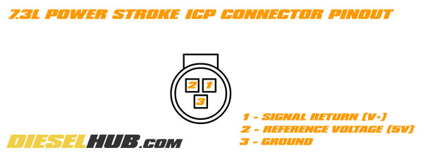
ICP sensor connector pinout diagram, 7.3L Power Stroke diesel
Resistor Color Codes
Always verify that you're using the correct resistor by using the chart below. Resistor codes, identified by the color and number of bands, are somewhat universal in the electronics industry. Resistors are easily obtainable at any electronics store, remarkably inexpensive, and available in a wide variety of sizes. A typical resistor is rarely labeled with its size and relies instead on the color coded band system outlined in the figure below.
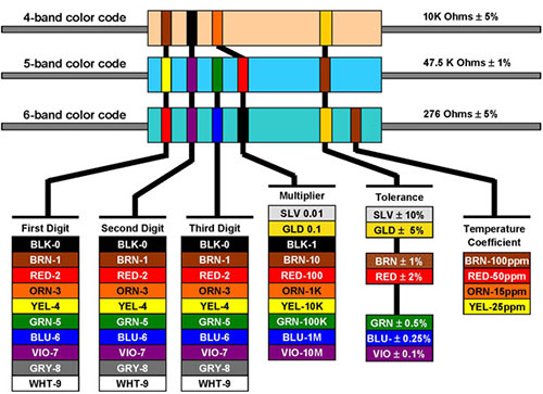
Resistor color code (band) chart
Parallel Resistor Circuit (10k)
The most common and/or "original" ICP resistor modification uses a 10k Ω resistor wired in parallel between the signal return and ground wires. It is common to complete this circuit by simply jumping the return and ground female pins inside the connector and then reinstalling it on the ICP sensor, where the resistor wires become wedged between the male and female pins of the sensor and connector respectively. This method is ill advised as it has a tendency to harm the pins of the sensor/connector. A weak or lost return signal can also develop do to engine vibration and the poor fitment of the connector to the sensor with the resistor forced in place. The proper way to wire this circuit is to make the appropriate cuts in the ICP sensor pigtail, solder the resistor in place, and protect the entire circuit with heat shrink tubing.

"10k mod" wiring diagram, 7.3L Power Stroke diesel
Series Resistor Circuit (5.6k)
The 5.6k mod is thought to have been developed later than the parallel wired 10k mod. A smaller 5.6k Ω resistor is generally recommended in this circuit do to the fact that the resistor is wired in series with the signal return, not parallel. However, there have been instances where a 10k Ω resistor has been used in series without any negative consequences. If wiring a resistor in series, it is recommended that you start with a 5.6k Ω resistor in order to identify how the engine responds.
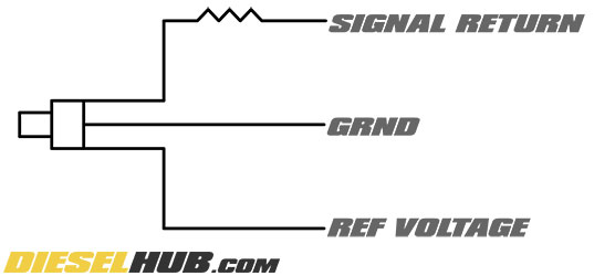
"5.6k mod" wiring diagram, 7.3L Power Stroke diesel
Switched Parallel Resistor Circuit (10k)
A switched version of the parallel 10k Ω circuit utilizes a dash mounted SPST (single pole, single throw) toggle switch so that the ICP sensor can be switched back to the factory settings by disconnecting the resistor ran between the signal return and ground wire of the circuit. This comes recommended as one of the most profound disadvantages of the 5.6k or 10k resistor mods is a rough idle. This circuit allows the resistor to be disconnected at idle (or as requested) so that the engine may run normally.
"10k mod" wiring diagram with switch, 7.3L Power Stroke diesel
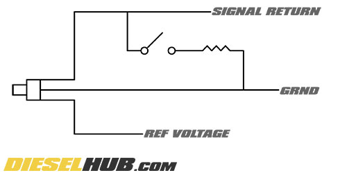
Switched Series Resistor Circuit (5.6k)
A switched version of the 5.6k mod can be accomplished using a SPDT (single pole, double throw) toggle switch mounted in the cabin. One throw of the toggle switch completes the 5.6k Ω resistor circuit, while the other returns the circuit back to normal. As with the parallel resistor circuit, a switch is recommended so that the modification can be deactivated.
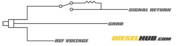
"5.6k mod" wiring diagram with switch, 7.3L Power Stroke diesel
Potentiometer Circuit (10k)
The most sophisticated ICP sensor resistor modification relies on a potentiometer or rheostat so that the resistance through the circuit can be adjusted at any time. Since a potentiometer is a controllable variable resistor, the resistance affecting the signal return can be changed with the turn of a knob. A 10k Ω potentiometer is generally used and wired in series with the signal return wire. Mounting the potentiometer in the cabin gives the driver the ability to essentially adjust power settings on-the-fly as well as return the system to the factory settings (0 Ω).
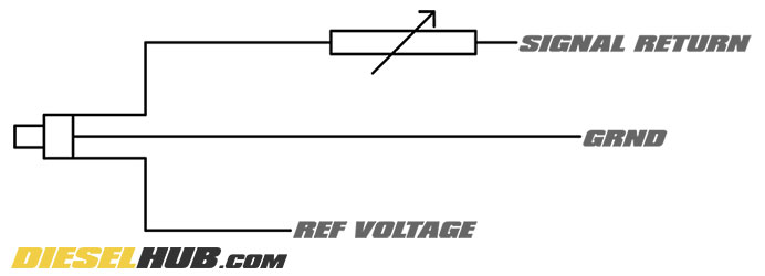
"10k mod" wiring diagram with potentiometer, 7.3L Power Stroke diesel