How a Turbocharger Works
A turbocharger is a forced induction device that recovers engine waste heat in order to increase performance and efficiency in a combustion engine. This is accomplished by utilizing otherwise wasted energy from the engine exhaust to compress the incoming air charge. A turbocharger draws in ambient air and compresses it, ultimately increasing the intake manifold pressure. The result is a higher density of air in the cylinders, raising the performance potential.
The components of a simple turbocharger include:
• Compressor housing
• Compressor wheel (compressor)
• Turbine housing
• Turbine wheel (turbine)
• A common shaft connecting the turbine and compressor wheels.
The compressor and turbines of a turbocharger rotate in unison - that is, both wheels rotate with exactly the same angular velocity. Therefore, for any force acting upon the turbine, an equal force is acted upon the compressor. This is the basis for recovering waste heat from the engine exhaust. As high velocity, high temperature gases are expelled from the combustion chamber, they travel from the exhaust manifold through the turbine housing. A portion of the energy contained in these gases is than transfered to the turbine and therefore compressor of the turbo. The turbine and compressor housings are isolated from one another - there is therefore no mixing of air and exhaust gases.
The geometry of the turbine is optimized to capture energy from the exhaust stream, while the compressor is optimized to pressurize the incoming air charge. In other words, compressor and turbine geometries (shape, size, fin design) are characteristically designed for separate purposes and are therefore different in appearance. The thermodynamic process by which waste energy is converted into usable mechanical power results in a temperature differential between the inlet and outlet of the turbine housing. While the turbocharger is in operation, the temperature of exhaust gases at the inlet of the turbine housing will always be greater than at the outlet of the turbine housing. The greater the temperature difference, the more energy extracted by the process.
A turbocharger increases performance by forcing air into the combustion chamber of each cylinder, increasing the volumetric efficiency. This is opposed to a naturally aspirated process, where air is drawn in by the vacuum created as the piston descends on the intake stroke. The greater volumetric efficiency of the forced induction process results in a denser charge of air and therefore higher quantity of air molecules present in the combustion chamber prior to the compression stroke. The greater amount of oxygen molecules present therefore allows for a greater quantity of fuel to be injected, resulting in higher power outputs.
The pressure a turbocharger creates is commonly referred to as boost - to make more boost is to create a greater manifold pressure (the pressure of the intake manifold is roughly equal to the pressure of air in the combustion chamber at the end of the intake stroke). Because compressing air proportionally increases its temperature, intercooling is common on turbocharged engines to further increase efficiency and performance potential. The efficiency of a turbocharger is not constant; efficiency can vary considerably depending on operating conditions such as speed and load.
A "large" turbo typically provides top-end power and higher airflow potential, while a "small" turbo exhibits quick spooling characteristics at the expense of lower overall airflow at higher engine speeds. In single turbo applications, selecting a turbocharger is a balancing act of meeting airflow requirements and minimizing turbo lag.
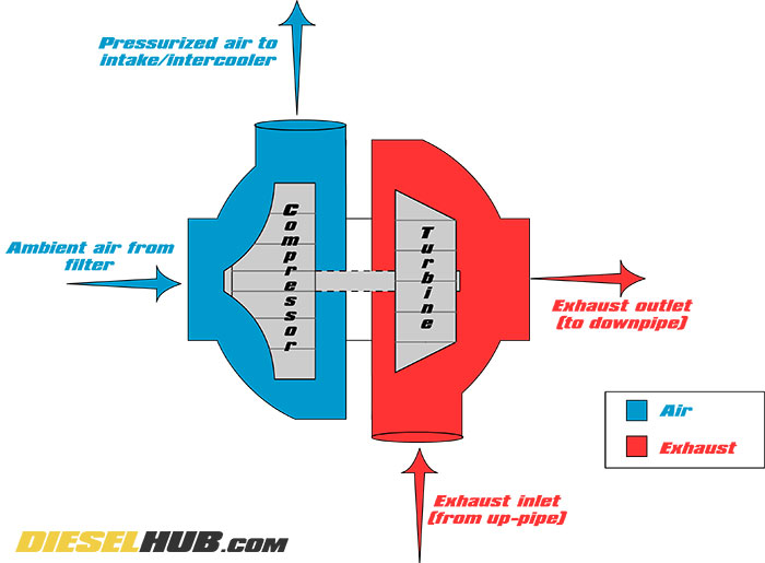
Operation of a typical turbocharger
Turbocharger A/R Ratio
The A/R ratio of a turbocharger goes by many names, including "aspect ratio", "area to radius ratio", "air ratio", and "area ratio". All these terms are synonymous with one another and refer to the ratio of the area of the turbine/compressor inlet to the distance between the centroid of the inlet and the center of the turbine/compressor wheel.
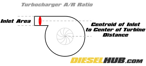
Turbocharger A/R ratio diagram
A/R ratios are typically discussed in reference to turbine housings as the A/R ratio of the turbine housing significantly impacts turbocharger performance, whereas compressor performance is less sensitive to changes in compressor housing A/R ratios. As a result, turbine housings are generally characterized by the A/R ratio, while the compressor side of the turbo is distinguished by the exducer/inducer diameters and trim.
Generally speaking, turbine housing A/R ratios exhibit the following characteristics:
Large A/R Ratio - The larger the A/R ratio, the slower the turbo spools (more lag, slower response). However, a large A/R ratio yields greater top end performance potential and efficiency in addition to lower backpressure and higher flow capacities.
Small A/R Ratio - The smaller the A/R ratio, the quicker the turbo will spool (less lag, better response). This is at the expense of flow capacity and lower performance overall. A turbine housing with a small A/R ratio will suffer from greater pumping losses, increased backpressure, and the turbocharger may choke on the top end. The flow velocity of exhaust gases into the turbine housing is higher.
Controlling Boost with a Wastegate
On a standard turbocharger (non-VGT), maximum boost pressure is controlled by a device called a wastegate. The wastegate is essentially a valve that can be internally or externally integrated into the turbine housing. When a predetermined boost pressure is realized, the wastegate opens and allows exhaust gases to bypass the turbine. In effect, the wastegate controls turbocharger outlet pressure by metering the amount of exhaust flow across the turbine. Exhaust gases that bypass the turbine housing expel directly into the exhaust system at the turbine outlet.
Variable Geometry Turbochargers
A variable geometry turbocharger features a series of operable vanes in the turbine housing that vary its geometry, increasing or decreasing the A/R ratio as necessary to provide optimal performance and efficiency at any combination of speed, load, and pressure. The vanes, which are actuated electronically, hydraulically, or by vacuum, open and close as commanded by the PCM in order to build or maintain boost pressure as necessary. This effectively allows a single turbocharger to display the characteristics of both a small and large turbo simultaneously.
With the vanes in the closed position, the effective size of the turbine housing is decreased and the A/R ratio reduced. In this position, the turbocharger may spool rapidly since the exhaust gases are more concentrated at the turbine wheel, in effect compensating for low exhaust flow.
As the vanes gradually open, the effective size of the turbine housing is enlarged and A/R ratio increased. In this position, the turbocharger can manage higher exhaust flow rates, exhibiting good overall performance characteristics without choking from high backpressure. A VGT turbo also uses the variable vane system in place of a wastegate - instead of using a valve to bypass exhaust flow, the vanes open, reducing the flow velocity and concentration of exhaust flow on the turbine wheel.
In addition to providing an optimal A/R ratio based on current operating conditions (load, speed, demand, etc), a VGT turbocharger can be used an exhaust brake by closing the vanes during acceleration, effectively increasing backpressure in the same manner that a typical exhaust brake would. OEM "exhaust brakes" are more often than not simply a selectable mode in which the VGT vane schedule is modified to provide braking.
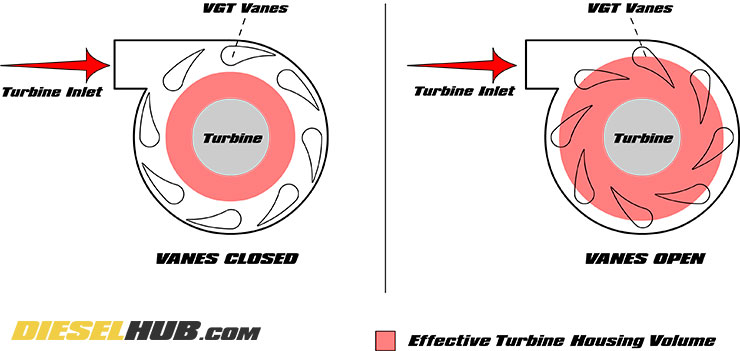
Operation of a typical variable geometry turbocharger
Aftermarket vs OEM Turbochargers
The design of turbo-machinery, including turbochargers, is a highly complex field that must account for a number of variables. There is no perfect turbocharger - selecting a turbocharger for an application is a process that requires giving up certain characteristics in order to obtain others. The performance of a turbocharger is a product of its geometry, with a definite focus on the flow characteristics of the housings and efficiency of the compressor and turbine wheels. The geometry of the compressor and turbine wheels is typically proprietary to a particular brand and/or product. This is where an aftermarket turbocharger may be considered an upgrade to an OEM unit. An upgraded turbocharger typically provides a variety of performance benefits, including greater airflow and maximum pressure potentials.
Another important topic in turbochargers is bearing design. Many OE turbochargers utilize journal bearings, which are cost effective and, for all intents and purposes, perform their task adequately. A journal bearing is essentially a bushing that that rests between the shaft of the turbocharger and the bearing race. The bushing, or sleeve, typically has holes that allow for high pressure oil to enter. The turbocharger shaft is then suspended on the thin film of oil between the shaft and journal bearing sleeve. While they are adequate in stock applications, longevity becomes a cause for concern with higher boost pressures realized in performance applications.
Ball bearing turbochargers feature ball bearings that suspend the shaft within the turbo housing. While lubrication is still essential, they do not necessarily need high pressure oil flow to ensure proper operation. In a ball bearing application, the turbo shaft is supported by the bearing cartridge, not a thin layer of oil. Ball bearing turbochargers operate with less friction than journal bearing turbos, thus decreasing turbocharger lag, increasing longevity, and tend to be more compatible in high boost applications. Keep in mind that a turbocharger can accelerate to more than 100,000 rpm in mere seconds.
You may need to consider upgrading your turbocharger system if...
• Engine is experiencing high exhaust gas temperatures (EGT)
• Engine is producing excessive black smoke under load, signaling a high air-fuel mixture
• Engine has extensive fuel system upgrades, which may include larger injectors and high performance injection pump(s)
• Engine suffers from excessive turbo lag/slow spool times
Performance increases resulting from turbocharger upgrades and swaps are difficult to estimate because each application will vary considerably. If your engine is running out of air (excessive smoke on the top end), or you're tired of putting up with turbo lag, a new turbocharger can make a huge difference. Turbochargers are generally advertised by the maximum horsepower range they can support, not how much horsepower they will add. Given you choose the proper turbocharger for your application, you can expect reduced turbo lag, increased hp/torque, and lower exhaust gas temperatures.
Twin Turbocharging - Sequential, Compound, & Parallel Turbo Systems
While a single turbocharger system can support a significant amount of power, a twin turbocharger system exhibits the high airflow potential of a large turbo while maintaining the quick spooling characteristic of a much smaller turbo. Twin turbos, albeit more expensive and complex, are unmatched in overall performance. There are two methods of installing twin turbochargers, in a sequential arrangement or a parallel arrangement.
Sequential/Compound Turbo Systems
In a sequential or compound turbo system, two turbochargers exhibiting considerably different characteristics are used. Compound turbo systems usually rely on a one small and one large turbocharger to obtain the characteristics of both - quick spooling with plenty of airflow to support massive amounts of horsepower. The smaller turbo is typically referred to as the "high pressure" turbo, while the larger turbo is typically credited as the "low pressure" turbo. In this arrangement, the low pressure turbocharger draws in ambient air through the air filter and feeds it to the high pressure turbo. On the exhaust side, exhaust exits the engine and into the low pressure turbo, then to the high pressure turbo. Air is first compressed in the low pressure turbo, then compressed even further in the high pressure turbo. The benefit is in the fact that the high pressure turbo spools rapidly, while the low pressure turbo moves a greater volume of air.
Parallel Turbo Systems
In a parallel twin turbo system, each turbocharger receives 1/2 the available exhaust flow. In a "V" engine, a single turbocharger is typically mounted the the outlet of each exhaust manifold. On an inline engine, parallel turbos can be mounted side-by-side at the outlet of the exhaust manifold by means of a split "Y" fitting. The theory in paralleling multiple turbochargers is that each turbo can be sized smaller than in a single turbo system, promoting rapid spool times. In practice, a parallel turbo system cannot typically outperform a compound turbo system in terms of maximum airflow, and thus they are largely (but not necessarily completely) impractical for diesel applications. The air side of a parallel turbo system meets at the intercooler or intake manifold, i.e. they feed both banks of cylinders jointly, not individually.