The General Motors 4L60E is a four speed automatic transmission employed in various rear wheel drive applications across GM's family of brands beginning in 1993. It is a direct descendant of the TH700R4, but with the adaptation of full electronic controls. The transmission has been used extensively in GM products powered by V-6 and V-8 engines. Subsequent variants, the 4L65E and 4L70E, were introduced to meet greater demands in applications with higher gross vehicle weight ratings and greater input torque requirements.
TH700R4 to 4L60E - A Brief History
General Motors introduced the TH700R4 four speed overdrive automatic transmission in 1982 as a replacement for the direct drive TH350. The timing was not entirely without warrant; oil prices surged in the late 1970's, and fuel economy was becoming a driving force in vehicle sales. The 700R4's 30% overdrive offered lower engine RPM at cruising speed and a significant increase in fuel mileage potential.
For 1990, GM adopted a new naming convention for their powertrain products and the designation was changed from the TH700R4 to the 4L60; 4 forward speeds, longitudinal configuration, and a relative input capacity of 60. For the 1993 model year, electronic controls were adapted to the 4L60 and the 4L60E, the "e" denoting electronic controls, was phased in.
There's often confusion over this new name convention; some resources suggest that the 60 correlates to a maximum GVWR of 6,000 lbs, but GM's own published data identifies that the transmission is suitable for applications up to 8,600 lbs. Others have suggested that the 4L60E is rated for a maximum input torque capacity of 600 ft-lbs (or even 600 N-m), but this is a far cry from the 350 ft-lbs that that the early 4L60E was rated for. Additionally, neither of these patterns fit other transmission models following the same name convention (4L65E, 4L70E, 4L80E, 4L85E, 6L50E, 6L90E, 10L80, etc). Rather, suffix of the transmission model is as a relative input torque capacity; the number does not correlate to an actual value, but an "80" designation would be a more robust unit than a "60" and a "90" designation would be stronger than an "80".
The C5 Corvette (1997 - 2004) featuring the 4L60E automatic transmission is unique in that the transmission is located in the rear of the car bolted directly to the rear differential. In lieu of a tailshaft housing, the tailshaft (output shaft) slides directly into the rear differential. Power is transmitted from the front mounted engine to the transmission by a driveshaft system called a torque tube. Removing the transmission requires dropping the rear suspension cradle; the transmission and differential are removed as one assembly. These applications utilize a unique transmission fluid pan with a small sump stamped into the bottom. A large plug threaded into the driver side of the fluid pan is used to check the transmission fluid level and add automatic transmission fluid; there is no dipstick.
4L65E & 4L70E Transmissions
Also within the 4L60E transmission family are the models 4L65E and 4L70E, strengthened versions of the 4L60E designed for greater capabilities and more potent engine platforms, including the LS family of small block Chevy's introduced in 1997. As GM's engine family evolved, their transmission lineup had to follow suit. Notable differences between the 4L60E and 4L65E/4L70E are a larger 300 mm torque converter and 5 pinion (versus 4 for the 4L60E) planetary gearset. Technical publications often do not refer to the 4L65E and 4L70E specifically by model and rather use the 4L60E as an umbrella term for all three models due to the extensive similarities between the three gearboxes.
4L60E Transmission Specs
Designation: |
General Motors 4L60E, 4L65E, 4L70E |
|
Type: |
4 speed automatic transmission, rear wheel drive |
|
Predecessor: |
General Motors 4L60/TH700R4 |
|
Applications: |
Various GMC, Chevrolet, Buick, Cadillac, Oldsmobile, and Pontiac vehicles from 1993 - 2014. Common applications include: 1993 - 2005 Chevrolet Astro For help identifying the 4L60E transmission, see ID information in section below |
|
RPO Code: |
4L60 |
MD8 |
4L60E |
M30 |
|
4L65E |
M32 |
|
4L70E |
M70 |
|
Production Plant(s): |
GM Powertrain Toledo Transmission Plant, Toledo, Ohio |
|
Overall Ratio/Total Ratio Spread: |
4.40 |
|
Gear Ratio Range: |
3.06 - 0.70 |
|
Average Gear Step: |
65% |
|
Control Type: |
Electronically controlled (electronic shift, line pressure, and torque converter clutch control); gas engines controlled by vehicle PCM, diesel vehicles (6.2L, 6.5L) controlled by standalone TCM |
|
Torque Converter: |
4L60E |
298 mm (11.73 inches) or 300 mm (11.81 inches, LS engines only) |
4L65E, 4L70E |
300 mm (11.81 inches) |
|
Torque Converter Lockup: |
Yes, actuated by electric solenoid (TCC solenoid) |
|
Stall Ratio: |
298 mm torque converter |
1.84 to 2.34 |
300 mm torque converter |
||
Input Shaft: |
30 spline |
|
Max Input Torque: [1] |
4L60E |
350 ft-lbs (488 N-m) nominal engine torque |
4L65E |
380 ft-lbs (515 N-m) nominal engine torque |
|
4L70E |
400 ft-lbs (542 N-m) nominal engine torque |
|
Maximum Shift Speed: |
6,000 rpm |
|
Maximum GVWR: |
8,600 lbs |
|
Case Length: |
21.9 inches |
|
Case Material: |
Die cast aluminum |
|
Transmission Weight: |
Approximately 155 lbs dry, 175 lbs with fluid |
|
PTO Provisions: |
None |
|
Service Intervals: |
Replace transmission filter and fluid every 100,000 miles under normal conditions or every 50,000 miles under "severe service" conditions [2] |
|
Transmission Fluid Type/Spec: |
GM DEXRON VI automatic transmission fluid (supersedes DEXRON III specification) Recommend Amsoil Signature Series FE synthetic ATF, a high quality full synthetic alternative |
|
Transmission Fluid Capacity: |
8.4 - 11.2 U.S. quarts (total fluid and service refill capacity will vary by application) |
|
Transmission Filter: |
Shallow pan [3] |
ACDelco TF-289 (GM 25174487) |
Deep pan [3] |
||
Corvette |
ACDelco TF-306(preferred) |
|
Transmission Pan Gasket: |
||
Transmission Pan Magnet: |
||
[1] - The input torque capacity of the 4L65E and 4L70E are often misquoted; as of 2022, Chevrolet is still offering aftermarket variations of these transmissions through their performance parts division. These "SuperMatic" transmissions are upgraded versions of the original factory units and offer higher input torque ratings than their OE counterparts.
[2] - Service intervals may vary by application and driving conditions; intervals for C/K series truck applications are shown. "Severe service" conditions typically apply to vehicles that are used to tow/haul frequently, are driven for long periods in high temperatures, or are frequently operated in heavy stop-and-go traffic conditions. Please refer to your owners manual for vehicle specific service information.
[3] - Shallow and deep pan transmission variants require different transmission sump filters; filters are not cross-compatible between pan types. Refer to sub-section below for more information on shallow and deep pan versions, including how to distinguish between the two.
4L60E Gear Ratios
Gear |
Ratios |
1st |
3.059 : 1 |
2nd |
1.625 : 1 |
3rd |
1.000 : 1 |
4th |
0.696 : 1 |
Reverse |
2.294 : 1 |
Gear Steps
Gear Change |
% Step |
1st to 2nd |
88% |
2nd to 3rd |
63% |
3rd to 4th |
44% |
4L60E Identification
The 4L60E features a simple, relatively square pan configuration secured to the bottom of the transmission by 16 bolts. This pan configuration is shared by the 4L60, but the two transmissions are easily distinguished; 4L60E transmissions have a large electrical connector pointing upwards on the passenger side near the center of the case (laterally); the hydraulically controlled 4L60 has no such connector. Shallow and deep style transmission pans have the same bolt pattern and only their depth is different. The subsection below contains details on identifying shallow and deep style transmission pans.
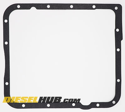
Figure 1 - 4L60E transmission pan gasket shape and bolt pattern
4L60E Variants & Model Year Changes
It would be an understatement to say that the 4L60E has gone through many changes through the course of its life; this transmission has been revised repeatedly, with some of the changes being more significant than others. Changes can be application specific and/or model year specific; some represent simple improvements, while others represent more pertinent modifications for reliability and durability purposes. Before attempting to service or repair a 4L60E, you will need to know exactly what year and/or style transmission is mated to your engine.
Shallow vs Deep Pan 4L60E
There are 3 transmission pan styles within the 4L60E/4L65E/4L70E transmission family. For all applications, save for the Chevrolet Corvette, the transmission has one of two pan styles; a shallow type or deep type fluid pan. The names are quite self explanatory, as one pan type is deeper than the other and holds a larger volume of transmission fluid. For the 1998 model year, GM attempted to synchronize the transmission pan type by application and all C/K series trucks and G series vans rolled off the assembly line with a deep style transmission pan while all other applications were equipped with a shallow style pan. This did not last indefinitely, and there does not seem to be any set list of specific applications that received each style pan. Fortunately, it is extremely easy to distinguish between the two pan styles.
4L60E equipped Corvettes are unique and feature neither a deep nor a shallow style pan; the transmission pan found on these rear mounted transmissions has a unique sump stamped into the pan and an integrated oil fill/oil level inspection plug on the drivers side. The C5 Corvette is the only application to use this style transmission fluid pan.
4L60E shallow pans are approximately 2-1/4 inches deep and the entire pan is one uniform depth. 4L60E deep pans are approximately 2-7/8 inches deep with a large 3/4 inch step upwards (reduced depth) near the front of the transmission pan (closest to the engine) and a smaller step at the rear driver side corner of the pan. Figure 2 below identifies a shallow type pan and figure 3 features a deep type pan.
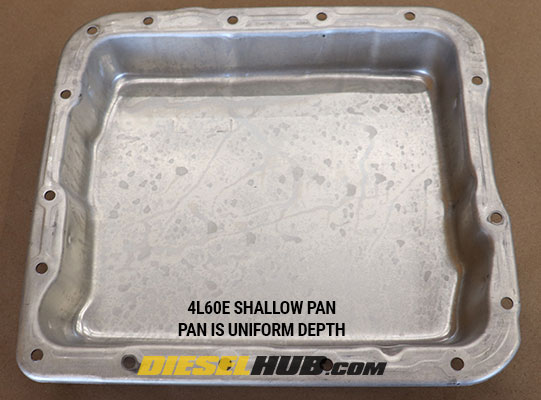
Figure 2 - 4L60E shallow style transmission pan; note the uniform depth
(factory GM transmission pan shown)
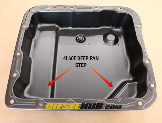
Figure 3 - 4L60E deep style transmission pan; note the difference pan depths due to the steps
(aftermarket transmission pan shown)
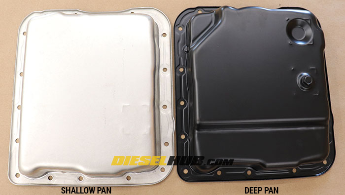
Figure 4 - Side by side comparison of the shallow and deep transmission pan styles found on the 4L60E transmission
Due to the differences in depth, the transmission sump filters are NOT interchangeable between a shallow and a deep style pan. The filter element is taller for deep pan versions due to the increased sump depth. Additionally, the Corvette requires its own unique transmission filter that is compatible with neither a shallow nor a deep style pan. The Corvette filter has an extension tube integrated into the filter housing that drops into its unique pan sump.
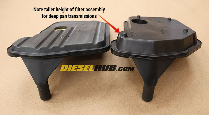
Figure 5 - Shallow vs deep style pan transmission filters
In addition to there being two different filter styles, there are several versions of each transmission filter available through General Motors. Figure 6 below, for example, compares an American made transmission filter to a Mexican made transmission filter, both of which are sold under the "Genuine GM" brand.
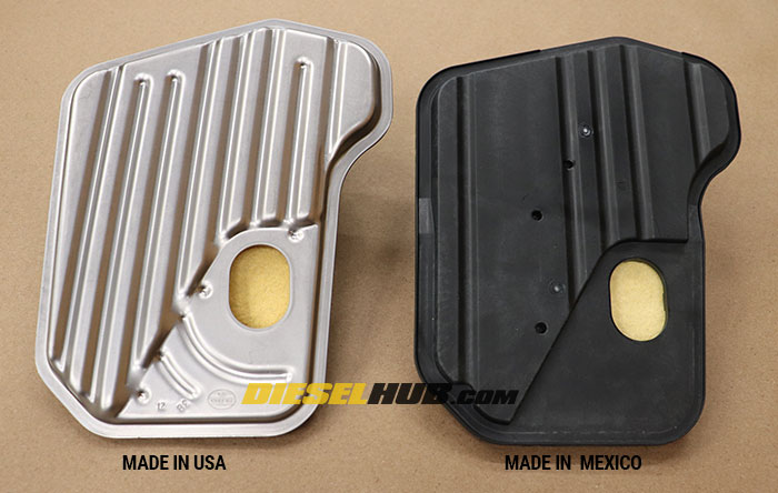
Figure 6 - Made in USA vs made in Mexico Genuine GM transmission filters
4L60E Changes & Updates
One of the most notable changes began in 1996 when GM began phasing in a version of the 4L60E with a removable bellhousing instead of an integrated one. This increased the adaptability of the transmission and was a critical revision that allowed the 4L60E and its variants to mate to the new LS engine family. In the process, the case was lengthened by approximately 0.75 inches. The phase-in began with V-6 engines at the beginning of the 1996 model year, but all 4L60E transmissions would feature the removable bellhousing by the start of the 1998 model year. The 300 mm torque converter was also introduced for the 1998 model year and was standard on all 4L60E transmissions mated to LS engines. 4L60E transmissions with the 300 mm torque converter have a physically larger bellhousing than versions with a 298 mm torque converter.
Model Year |
Summary of Changes |
1995 |
Pulse width modulated (PWM) torque converter clutch apply feel solenoid added to "ramp" torque converter clutch instead of applying rapidly with an on-off type solenoid; resulted in smoother TCC apply. |
Revised transmission oil pump introduced to function with new PWM TCC apply feel solenoid; revised pump stamped "PWM" and not interchangeable with previous pump types. |
|
1996 |
New valve body design with improved exhaust path for low/reverse clutch; increased service life. |
All C/K trucks and G series vans receive push-in (quick connect) oil cooler fittings instead of previous threaded type fittings for ease of assembly. |
|
Revised vehicle speed sensor (output shaft speed sensor) and new tailhousing casting to accommodate smaller diameter sensor bore, location moved from driver side to passenger side; all applications except Corvette (adopted in 1997). |
|
Phase-in begins for removable tailhousing to expand engine applications for 4L60E transmission. |
|
Revised 3-2 downshift control solenoid with simple on-off functions (previous solenoid used PWM) and new 3-2 downshift valve; improved 3-2 downshift and increased the service life of the 2-4 band. |
|
1997 |
Corvette 4L60E adopts passenger side mounted vehicle speed sensor (as detailed above). |
Revised transmission oil pump with new 13 rotor pump design replacing the previous 10 rotor pump; implemented to reduce/eliminate whining noise generated by previous style transmission pump. |
|
1998 |
Phase-in of removable bellhousing completed by beginning of the 1998 model year. 300 mm torque converter version of the 4L60E introduced for LS engine applications. |
All C/K trucks and G series vans equipped with deep style transmission pan; all other applications come factory equipped with a shallow type pan, except for the Corvette. It is unknown how long this was standard, but trucks would eventually begin receiving shallow or deep pans depending on the application type. |
|
New torque converter clutch solenoid; connector and solenoid body revised to help distinguish it from the 3-2 downshift control solenoid. |
|
Unused groove removed from the stem of shift solenoids A and B to prevent installing the retaining clip in the wrong groove (solenoid would not be fully seated if clip was installed in the foremost groove instead of the correct one). |
|
Larger micron filter screen adapted to nose of pressure control solenoid assembly to improve cold weather performance (less restrictive, improved flow when transmission fluid is cold and thick). |
|
2001 |
4L65E model transmission introduced. |
2006 |
4L70E model transmission introduced. |
4L60E vs 4L65E vs 4L70E
The 4L65E and 4L70E are strengthened adaptations of the 4L60E. From the exterior, the transmission case features are identical; the differences lie inside. One significant difference is that the 4L65E/4L70E employ 5 pinion front (input) and rear (reaction) planetary carriers, as opposed to the 4 pinion versions found in the 4L60E. Spreading the load across 5 pinions reduces the load in each pinion and makes for a more resilient system with a higher torque capacity. Additionally, the 4L65E and 4L70E utilize 7 friction clutches in the 3-4 clutch pack, as opposed to the 6 clutches found in the 4L60E. The additional clutch provides greater holding capacity and increases the load capacity of the 3-4 clutch pack. All 4L65E and 4L70E transmissions feature a 300 mm torque converter (11.81 inch diameter) while the 4L60E typically uses a 298 mm (11.73 inch diameter) torque converter; 4L60E transmissions mated to LS engines will use the 300 mm converter, requiring a larger bellhousing than the 298 mm versions.
4L60E Shift Solenoids & Electronic Inputs
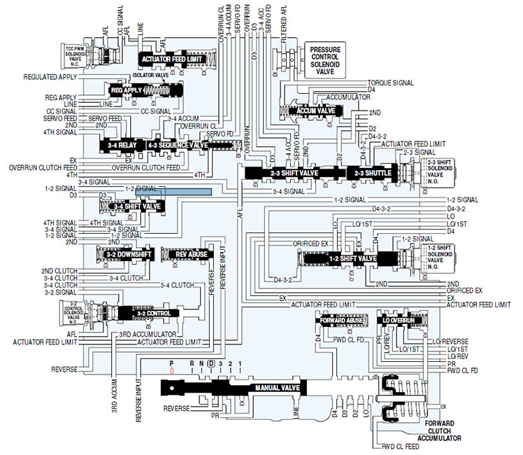
Figure 7 - 4L60E shift solenoid, valve, and accumulator locations (valve body schematic)
Torque converter clutch solenoid (TCC) - As the name would suggest, the TCC solenoid is responsible for applying and releasing the torque converter lockup clutch. It is a normally open solenoid, thus transmission fluid pressure in this circuit is exhausted when the solenoid is deactivated. When activated, pressure in the circuit builds and the TCC valve advances to the apply position.
Transmission pressure control solenoid - The transmission pressure control solenoid is used to regulate line pressure based on PCM inputs that include throttle position. The duty cycle of the pressure control solenoid is directed by the PCM, which will deliver an electrical current between 0 and 1.1 amps. No current flow to the solenoid results in 0% duty cycle while 1.1 amp current flow applied to the solenoid results in a 60% duty cycle (peak duty cycle for this solenoid). Furthermore, 0 amps corresponds to maximum line pressure while 1.1 amps results in maximum line pressure; if electrical power to the solenoid is interrupted, the transmission will operate at maximum line pressure.
1-2 and 2-3 shift solenoids - The 1-2 (solenoid A) and 2-3 (solenoid B) shift solenoids actuate the 1-2 and 2-3 shift valves. They are normally open, allowing transmission fluid in the corresponding circuit to exhaust until commanded. When commanded closed by the PCM, fluid flow is redirected to the corresponding shift valve to initiate a shift sequence. These two solenoids work in four different combinations to select different gear ratios in the transmission.
3-2 control solenoid - The 3-2 control solenoid is used to enhance the 3-2 downshift and reduce harshness by smoothly releasing the 3-4 clutch and applying the 2-4 band. Early units used a PWM solenoid, whereas 1997 and newer transmissions utilize a simple on-off type solenoid.
Transmission fluid pressure switch assembly (PSA) - The fluid pressure switch assembly is a series of five pressure switches integrated into the transmission valve body. Each pressure switch delivers 12 volts to the PCM when there is fluid pressure in that particular oil circuit of the transmission. The logic of the fluid pressure switch circuit provides three output signals to the PCM, which are used to help determine shift solenoid operation, line pressure control, and torque converter lockup. The transmission fluid temperature sensor is also integrated into the PSA.
Transmission fluid temperature sensor (TFT) - The transmission fluid temperature sensor is used to help determine the torque converter lockup function and overall shift quality. It is a thermistor type sensor, meaning the internal resistance across the input and output signal will vary with the temperature of the sensor. Specifically, the TFT is a negative temperature coefficient thermistor; the resistance across the input and output decreases as the temperature of the sensor increases. The TFT uses a 5 volt input signal, thus the output signal to the PCM will vary between 5 (low temperature) and 0 (high temperature) volts.
Vehicle speed sensor (VSS) - The vehicle speed sensor measures the output shaft speed of the transmission and is used to determine shift points and calculate torque converter clutch slip. On four wheel drive vehicles, the VSS is located through the transfer case, while two wheel drive vehicles have the VSS mounted through the transmission tailhousing.
Input shaft speed sensor (ISS) - The input shaft speed sensor is only found on the 4L70E variant in the 4L60E transmission family. An input shaft speed sensor was added to the transmission in order to further refine the shift schedule logic by providing an input speed signal to the PCM.
Solenoid Apply Chart
A solenoid that is "ON" is in an energized state whereas a solenoid that is "OFF" is de-energized (i.e. no voltage to solenoid). In the event that both the 1-2 (solenoid A) and 2-3 (solenoid B) shift solenoids lose power, the transmission will be mechanically engaged in 3rd gear and will cease to shift. This design is implemented intentionally as a failsafe (sometimes called "limp mode") so that a vehicle can be driven to a safe location for diagnostics and repairs, even if the transmission has a significant fault.
Range Position |
Gear |
1-2 Solenoid (A) |
2-3 Solenoid (B) |
Park |
--- |
ON |
ON |
Reverse |
--- |
ON |
ON |
Neutral |
--- |
ON |
ON |
Overdrive (OD) |
1st |
ON |
ON |
2nd |
OFF |
ON |
|
3rd |
OFF |
OFF |
|
4th |
ON |
OFF |
|
Drive (D) |
1st |
ON |
ON |
2nd |
OFF |
ON |
|
3rd |
OFF |
OFF |
|
2 |
2nd |
OFF |
ON |
1 |
1st |
ON |
ON |
Transmission Connector Pinout Diagram
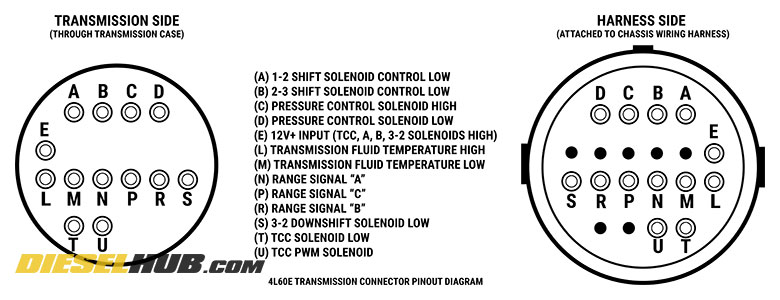
Figure 8 - 4L60E transmission connector pinout diagram
Note that the shift solenoids receive positive vehicle voltage (nominally 12v+) at all times that the ignition switch is positioned to "run". In order to actuate a solenoid, the PCM (or TCM in diesel models) completes the ground to the solenoid. In the case of pulse width modulated (PWM) solenoids, this is done at a particular duty cycle rather than using basic "on" and "off" states. 12v+ inputs to a solenoid are called the high side, while PCM switched grounds are called the low side. High (12v+) and low (ground) are labeled in the pinout diagram above for all relevant components.
Shift Solenoid Resistance Values
Sensor/Solenoid |
Case Connector Pins |
Resistance |
Pressure control solenoid |
C to D |
3.5 - 8.0 Ω |
1-2 shift solenoid (solenoid A) |
E to A |
20 - 40 Ω |
2-3 shift solenoid (solenoid B) |
E to B |
20 - 40 Ω |
3-2 control solenoid |
E to S |
9 - 14 Ω |
Transmission fluid temperature sensor |
L to M |
2.9 - 4.0 kΩ [1] |
Torque converter clutch solenoid |
E to T |
20 - 40 Ω |
[1] - Resistance value will vary with temperature; resistance should read approximately 3,600 Ω at 70° F.
Corvette Unique Service Procedures
The 1997 - 2004 C5 Corvette is a unique application of the 4L60E automatic transmission. In this configuration, the engine is located in the front of the vehicle but the transmission is mounted in the rear, bolting directly to the rear differential housing (there is no transmission tailshaft housing). A drive system called a "torque tube" transmits power directly from the engine to the transmission torque converter. While this powertrain configuration places more weight on the rear of the vehicle for improved handling, it complicates otherwise standard service procedures. Figure 10 below displays a recently replaced 4L60E automatic transmission in a 2000 Corvette C5.
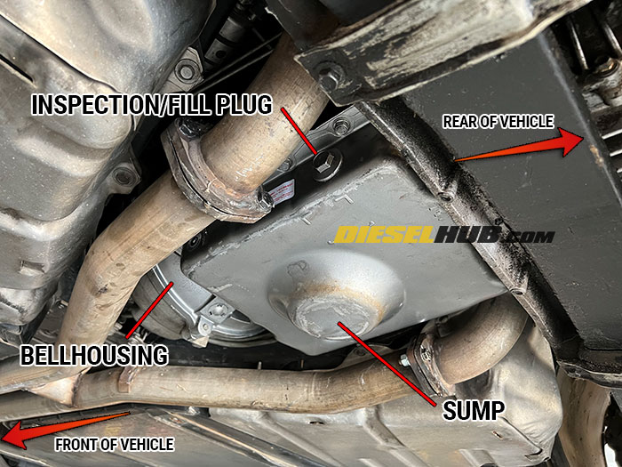
Figure 9 - Rear mounted 4L60E transmission in a C5 Corvette
Transmission Service Procedures & Fluid Level Check
The 4L60E found in Chevrolet Corvette's employs a unique transmission fluid pan with a small sump positioned in the center of the pan. A large plug on the driver side of the transmission is removed to check the fluid level and/or add transmission fluid. This procedure is to be performed with the engine running and gear selector in the park (P) position. When the transmission fluid is at the correct level, it will be above the inspection plug height when the vehicle engine is off. Removing the plug with the engine off will therefore allow transmission fluid to drain out of the pan and the fluid level will be low. It is only when the engine is running and fluid is flowing through the transmission, torque converter, and oil cooler lines that the transmission fluid level can be checked/adjusted. Furthermore, a unique transmission filter is required for this application due to the sump in the transmission pan; do not attempt to install a standard deep or shallow style transmission filter.
Transmission Fluid Level Check procedures
Note - take any and all necessary safety precautions; working beneath a running vehicle that is raised on a lift or hoist is extremely dangerous. Do not attempt if you are not qualified to work under such conditions.
1) Allow the transmission fluid to reach normal operating temperature by driving the vehicle.
2) Raise the vehicle using an appropriate car lift or hoist; the vehicle must be level and you must have access to the rear undercarriage.
3) Start the engine and ensure that the vehicle is park (P) and that the emergency/parking brake is applied.
4) Remove the fluid level inspection plug on the driver side and inspect the fluid level. The transmission fluid level should be to the bottom lip of the inspection plug hole.
5) Replace the inspection plug.
Adding Transmission Fluid
1) With the fluid level inspection plug removed, the engine running, and the transmission in park, pump ATF into the pan through inspection hole until fluid begins to drip out of the inspection plug hole and the transmission fluid level has reached the bottom lip of the hole.
2) Replace the inspection plug.
3) With the brake pedal applied, move the gear selector through all positions (P-R-N-D-3-2-1), then return to the park (P) position; repeat this process up to 2 additional times.
4) Recheck transmission fluid level as add as necessary. Recommend verifying fluid level once more after taking vehicle for a short drive.
Transmission Removal & Replacement
To remove a 4L60E transmission from a Corvette, the entire rear suspension cradle must be removed. After the cradle is removed and set aside, the transmission torque converter is disconnected from the torque tube adapter. The transmission and rear differential are removed as one assembly; installation is reverse. Although spacial constraints make the process appear burdensome, the task is much more intimidating than it is difficult.
If a new transmission is installed, ensure that the transmission fluid level is to the inspection plug level before starting the vehicle. After starting, continue to add fluid per the procedures outlined above until the fluid level is correct. Recheck and adjust the fluid level after driving the vehicle and allowing the fluid to reach operating temperature.
GM Transmission Name Convention
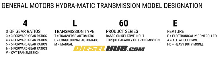
Figure 9 - General Motors Hydra-Matic transmission name convention
Summary & Key Points
• The GM 4L60E, 4L65E, and 4L70E automatic transmissions are based on the TH700R4 four speed overdrive transmission.
• These three TH700R4 variants range in max rated input torque, with the 4L60E having the lowest and the 4L70E having the highest maximum input torque rating.
• A shallow pan and deep pan variant of these transmissions coexisted; the transmission filters are not cross compatible between shallow and deep pan transmissions, so it is important to identify which version is mated to your vehicle before servicing.
Page Information
Last update: 10/19/2022
Copyright: Diesel Hub (dieselhub.com), all rights reserved
Source(s): GM Powertrain division