Applicable Models:
1999 - 2010 Ford F-250, F-350, F-450, F-550 Super Duty
Applicable Engines:
7.3 Power Stroke
6.0 Power Stroke
6.4 Power Stroke
6.8 Triton V10
Applicable Transmissions:
ZF S6-650, ZF S6-750 six speed manual
Hydraulic Master-Slave Clutch System Basics
A hydraulic clutch system is disengaged using a master and slave type system, which is comprised of four primary components; the clutch master cylinder, the clutch slave cylinder, the hydraulic fluid reservoir, and a hydraulic line connecting the master and slave cylinders. The concept is simple; a mechanical force created by the operation of the clutch pedal is converted to hydraulic pressure in the clutch master cylinder and converted back to a mechanical force by the clutch slave cylinder. Figure 1 below identifies the very basic operation of such a system.

When compared to a traditional mechanical linkage, the primary benefits of the hydraulic clutch actuation system include:
- More consistent pedal feel - the force applied by the slave cylinder is more consistent because it does depend on the angle of the lever arm in a mechanical linkage.
- Reduced pedal force - a very high mechanical advantage is achieved in the hydraulic system.
- Maintenance free - unlike mechanical linkages, a hydraulic master-slave system typically requires no adjustment.
The hydraulic clutch system is not without its drawbacks, which include:
- Prone to leaks - seals throughout the components are repeatedly exposed to high fluid pressures and can develop crippling leaks.
- Lower overall service life - the hydraulic components have a significantly lower overall life expectancy than a simple mechanical linkage.
- Air in the system can hinder operation - the initial bleeding of a hydraulic master-slave system can be difficult do to the small diameter line and orifices. Air in the hydraulic system has significant adverse effects on clutch releasing because it is a compressible fluid.
- Less reliable than a mechanical system - there are significantly more ways for a master-slave system to experience a failure than a traditional mechanical linkage.
Linear vs Concentric Slave Cylinders
There are two basic types of slave cylinders, linear and concentric. Linear slave cylinders are generally mounted externally through the transmission bellhousing. As the piston extends outwards, it acts upon a lever that releases the throwout bearing. Concentric slave cylinders (figure 2 below) are internally mounted and the throwout bearing is often an integral part of these assemblies. The transmission input shaft is installed through the center of the slave cylinder, which is situated behind the clutch pressure plate.

The obvious advantage of the external slave cylinder is that all components can be replaced without removing the transmission from the vehicle. In the case of concentric slave cylinders, the transmission must be completely removed from the vehicle to access the part. All ZF S6-650 and S6-750 transmissions found in Ford applications employ an externally mounted linear slave cylinder. All GM S6-650 transmissions utilize an internally mounted concentric type slave cylinder.
Symptoms of a Bad Master or Slave Cylinder
Clutch master or slave cylinder failures are generally quite obvious because either failure causes a condition where the clutch will disengage fully. Internal seals within the components are the most common cause of failure. A simple o-ring failure can allow fluid to seep past a piston, resulting in a master cylinder that will not build/hold pressure or a slave cylinder that won't move under pressure. Depending on the seal(s) that are compromised, an external leak may or may not be present. Note that an external leak is a very obvious sign of a component failure.
The o-rings that seal the hydraulic line to each component can also fail, but we consider this a more rare condition. The hydraulic line itself could also develop a leak or burst, but this too is rare. In these cases, the line is generally exposed to extreme heat (too close to an exhaust component) and/or has contacted and rubbed against another component, creating a weak spot. When installing master and slave cylinder components, always ensure that the hydraulic line is routed safely and securely.
Cause of Repeated Failures or Short Component Life
Repeated slave cylinder failures or a seemingly short slave cylinder life could be indicative of a severely worn clutch. As the clutch friction material wears, it changes the force required to disengage the clutch and increases the distance that the throwout bearing must travel to achieve disengagement. The slave cylinder must therefore work harder and extend further as the clutch wears. If you find yourself frequently installing slave cylinders, it may very well be time for a new clutch. The difference in pedal feedback between a brand new and a severely worn clutch is actually quite significant.
Clutch Pedal Pin Inspection
After the clutch master cylinder pushrod is removed from the pin welded to the clutch pedal armature, the pin should be inspected for wear. It is widely common for the plastic pushrod eyelet bushing to became damaged or lost, allowing metal-on-metal contact that quickly wears down the pin. Figure 3 below identifies a several worn pin on the pedal arm, causing significant play between the two components and poor clutch disengagement characteristics.

This condition requires replacement of the pedal assembly. A preventative modification, commonly dubbed the "heim joint mod", is available for 1999 to 2003 model year Super Duty trucks equipped with the ZF 6 speed transmission. This upgrade (RT-130101-SD) replaces the eye of the master cylinder pushrod with a spherical rod end and the pedal pin with a high strength bolt. The result is a non-wearing, maintenance free system with no play between the pushrod eye and pedal pin. Although this upgrade can be installed at any time, it is much easier to do while the clutch master cylinder is removed from the vehicle.
Applicable Parts & Part Numbers
Ford has essentially discontinued replacement clutch master and slave cylinders for most ZF 6 speed transmissions and the part numbers have become obsolete, with the exception of complete assemblies for some of the later applications. For the most part, the 1999 to 2004 Super Duty utilized a remote fluid reservoir while 2005 to 2010 trucks used an reservoir integrated into the master cylinder assembly. 2005 was a transition year and some early trucks may still use the remote reservoir.
At time of publishing, pre-filled kits were available for all applications; these include the master cylinder, slave, cylinder, fluid reservoir (if remote), and fluid line. If using a pre-filled kit plan on bench bleeding it to verify there is no air in the lines. Although they are sometimes touted as "pre-bled", it is easy enough to verify on your own. Installation and bleeding information is available in great detail in the bleeding and procedural subsections below. We do recommend replacing the master and slave cylinders together.
Perfection Clutch and Luk are the two brands we've provided part numbers for in the table below. Luk is a well known manufacturer in the clutch and clutch component space. The components from Perfection Clutch (also Brute Power) generally have cast aluminum housings instead of plastic. We have had many positive experiences with products from both brands. If you plan on replacing the hydraulic line, we recommend a pre-filled assembly in lieu of acquiring the components individually.
| Description | Part Number(s) | Remarks | |
|---|---|---|---|
| Clutch slave cylinder | 1999-2004 | Perfection Clutch 360108 Luk LSC369 |
--- |
| 2005-2010 | Perfection Clutch 900161 Luk LSC624 |
||
| Clutch master cylinder | 1999-2004 | Perfection Clutch 350135 Luk LMC376 |
--- |
| 2005-2010 | Perfection Clutch 800082 Luk LMC632 Ford 7C3Z-7C522-E |
||
| Clutch master-slave assembly | 1999-2004 | Perfection Clutch PF9021 Luk CRS021 |
[1] |
| 2005-2007 | Performance Clutch PF9094 Luk CRS023 Ford 6C3Z-7C522-C |
||
| 2008-2010 | Luk CRS044 Ford 7C3Z-7C522-E |
||
| Clutch hydraulic fluid | DOT 3 brake fluid, Motorcraft PM-1-C | [2] | |
| Master cylinder pushrod bushing eliminator | RT-130101-SD | [3] | |
[2] - Do not substitute with other oils or fluids.
[3] - Fits 1999 to 2003 model year Ford Super Duty.
Bleeding the Hydraulic Master-Slave Clutch System
Bench Bleeding
Bench bleeding is the process by which the master-slave system is bled with the components entirely assembled outside of the vehicle. When the components are installed on the vehicle, all air has been removed from the system and it is ready to be used. This is accomplished by actuating the slave cylinder pushrod repeatedly from the fully extended to fully retracted positions. Ideally, the slave cylinder is held at a position that is lower than the master cylinder and fluid reservoir, allowing gravity to aid in the displacement of all air from the component cavities and hydraulic line.
It is important to note that the clutch master cylinder pushrod should never be actuated until the slave cylinder is installed against the transmission release bearing lever. When the slave cylinder has nothing to restrict the pushrod from overextending, actuating the master cylinder risks damaging the seals in the slave cylinder. Only the slave cylinder is actuated with the components removed from the vehicle. As the name would suggest, bench bleeding is best performed on a workbench, preferably with a vice handy. The bench bleeding process is included in the master and slave cylinder removal/installation procedures below.
Bleeding After Installation
We've covered this topic repeatedly for various manual transmission models, but bench bleeding is far superior and the results are more consistently favorable. Bleeding air from the hydraulic clutch system becomes increasingly more difficult and tedious once the components are installed - not to mention, it tends to make a sizable mess. But in a pinch, it's worth knowing that there is an alternative or additional method of bleeding the system.
This method is similar to bleeding the brakes on a vehicle without a vacuum device. In other words, the old fashioned way where one person slowly depresses the brake pedal while another opens the bleed valve at the caliper/brake cylinder, then closes it before the brake pedal reaches the end of its travel. Actually, this is exactly how the clutch master/slave cylinder can be bled after installation. One person slowly depresses the clutch pedal while the other cracks open the bleed valve integrated into the body of the slave cylinder. There are three important notes about this process.
First and foremost, the slave cylinder bleed valve must not be opened until the clutch pedal has begun to be depressed and must be closed before the clutch pedal reaches the end of its travel. If either of these conditions are not met, air will enter the system. When the procedure is performed properly, the two persons must be in constant communication so that the bleed valve is opened only after the clutch pedal has began to be depressed (system pressurized) and it is closed prior to reaching the end of its throw.
Second, brake fluid is going to exit from the bleed valve at a relatively high velocity while it is open and there is pressure in the system. Attempts should be made to keep the fluid from covering nearby components. The person opening and closing the bleed valve should equip themselves with proper PPE, especially safety glasses or another form of appropriate eye protection.
Finally, do not forget to frequently check and top off the fluid reservoir level. If the fluid level drops below a certain threshold, air will enter into the system and the process will need to be repeated from the beginning. Don't forget the cap - if you depress the clutch pedal without the fluid reservoir cap in place, a solid stream of pressurized brake fluid is going to find its way all over your engine compartment and workspace.
Gravity Bleeding
Gravity bleeding is a method that occasionally works to remove air from the clutch system. It generally still requires the previously outlined manual bleeding technique to get every bit of air out of the slave cylinder, but it at least provides a starting place. With an appropriate container placed below the slave cylinder and the fluid reservoir full (cap off), open the bleed valve on the slave cylinder and let fluid begin to slowly drain from it. As it dribbles into the catch pan, monitor and maintain the fluid reservoir level. After refilling the reservoir several times, close the bleed valve. Top off the clutch fluid level, reinstall the fluid reservoir cap, and test for proper operation. This method rarely removes all air from the system, but it does provide a good starting place if you've opted out of bench bleeding.
ZF 6 Speed Clutch Master & Slave Removal, Installation, & Bleeding Procedures
Note that the order of these procedures is not concrete and certain steps can be rearranged. These procedures only apply to transmissions equipped with an externally mounted slave cylinder; concentric type slave cylinders are not covered in this section.
Click any thumbnail to view fullsize, detailed image

- Locate the clutch slave cylinder mounted through the upper portion of the bellhousing on the driver side.

- Trace the hydraulic line from the rear of the clutch slave cylinder and unclip it at any point where it is mounted to the frame or body. It is easier to remove the slave cylinder if the hydraulic line is free to maneuver beneath the vehicle.
- Remove the slave cylinder by rotating it counterclockwise (when looking from the rear to the front of the vehicle) until it is freed. A hex shape integrated into the rear of the casting allows a 1-3/16 wrench (or Crescent wrench) to be used if necessary.
- Let the slave cylinder dangle beneath the vehicle at this time.

- Trace the clutch pedal until the clutch master cylinder pushrod is located towards the driver side of the pedal arm.
- Disconnect the pushrod from the pedal arm by sliding the eyelet off of the pin.

- Orient and remove the clutch interlock switch. The lid of the switch is secured by two tabs located on either side of the device. A small flat-blade screwdriver can be used to dislodge the clips (pictured). If desired, or necessary, remove the connector from the switch to make it easier to maneuver; the area beneath the dash is not particularly spacious.

- Locate the clutch master cylinder protruding through the firewall.
- Remove the clutch master cylinder by rotating it clockwise (while looking at the firewall from the front of the vehicle) approximately 1/4 turn, then pulling the pushrod out through the opening in the firewall.

- Let the clutch master cylinder rest on the fender.
- If master cylinder has an integral fluid reservoir you may skip the next step, which only applies to models with a remote fluid reservoir.

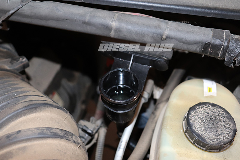
- Locate the clutch master cylinder fluid reservoir by tracing the hydraulic line.
- Remove the clutch fluid reservoir by relieving the (2) body clips securing it to the wiring harness mount.
- Carefully maneuver the clutch slave cylinder, master cylinder, and fluid reservoir out of the vehicle. This can be done by pulling the slave cylinder upwards through the engine compartment (recommended) or maneuvering the reservoir/master cylinder down beneath the vehicle.

- The hydraulic line connects the master and slave cylinders using a roll pin keeper. To disconnect the line from either component, drive out the roll pin with a 1/8 or 5/32 inch punch.

- All components come with a replacement seal and roll pin; neither the old roll pin nor seal should be reused. Lightly coat the seals in clean oil prior to installation.
- Replacing and installing the required components is as simple as reinserting the hydraulic line and securing it in place by driving in the roll pin.
- Replace all necessary components and/or assemble all new components as required. Do not operate any of the components at this time.

- Mount the clutch fluid reservoir in a vice or against the side of the workbench and place the slave cylinder on or near the ground. To bench bleed the system thoroughly and efficiently, the reservoir must be mounted at a higher level than the master cylinder and the master cylinder must be mounted at a higher level than the slave cylinder (pictured - reservoir mounted in vice, master cylinder laying on workbench, slave cylinder hanging off the edge of the workbench.

- Fill the clutch fluid reservoir to the fill line with DOT 3 brake fluid, then secure the cap.
- Under no circumstances should the clutch master cylinder be operated until the slave cylinder is installed in the transmission. It is not necessary to operate the master cylinder in order to bench bleed the system.

- Remove the slave cylinder retainer clip by forcing the pushrod inwards and releasing the plastic clips from their circular locks.
- Do not actuate the clutch slave cylinder with the fluid reservoir cap removed; fluid will evacuate the reservoir at high velocity. Always reinstall the cap before pumping the slave cylinder.

- With the slave cylinder at a height that is lower than the master cylinder, manually pump the slave cylinder by pushing the pushrod inwards, then allowing it to spring outwards. Repeat this action 10 to 15 times or until all air is removed from the system. Check and top off the fluid reservoir level every 2 to 3 cycles. If the reservoir level gets too low, air will be reintroduced into the system.
- The slave cylinder actuation will feel firm and consistent when all air is removed from the system, but you may wish to continue to bleed several more cycles. You will also notice that the fluid reservoir level stays constant once air is removed completely.

- Once the system is believed to be bled, maneuver the slave cylinder beneath the vehicle.

- Reinstall the clutch master cylinder and fluid reservoir in the reverse order that they were removed.
- When reinstalling the clutch master cylinder pushrod to the pedal assembly, do not forget the plastic eyelet bushing.
- Remove the clutch fluid reservoir cap and verify the fluid level; adjust as necessary, then reinstall the cap.

- Pump the slave cylinder by hand several more times and verify that it still feels firm and requires consistent force.
- Push the slave cylinder pushrod inwards and reinstall the retaining clip (as pictured).
- Install the slave cylinder in reverse order. The tabs on the retaining clip will break loose the first time that the clutch pedal is depressed.
- Re-secure the hydraulic line to the body/frame and ensure it is not touching an exhaust manifold.
- Depress the clutch pedal and test for proper operation of the hydraulic clutch system.

