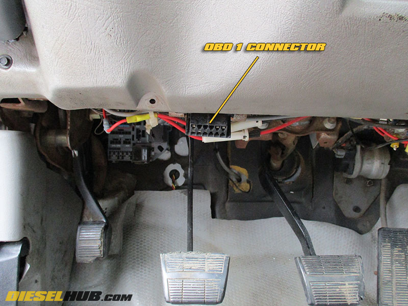
The OBD I connector is located beneath the dash and just left of the steering column. For reference, it is almost directly above the clutch pedal on trucks equipped with a manual transmission (click image at left to view fullsize). As previously mentioned, these procedures are applicable to pre-1996 model year trucks equipped with the 6.5L GM/Detroit diesel. 1996 and later model year trucks will feature an OBD II system, which is completely different and more sophisticated than the earlier diagnostics feature. There are several code readers that will read the DTCs stored in an OBD I system, however they can also be read without the need for special equipment. Refer to the connector pinout diagram and procedures below in order to read any stored DTCs from your 1992 through 1995 6.5L diesel.
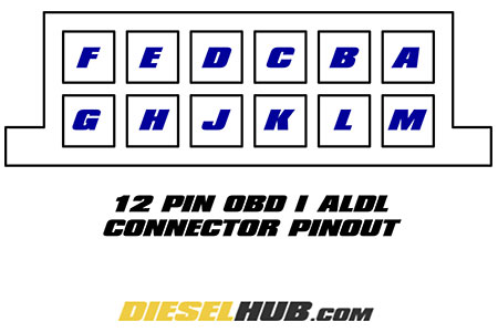
Pinout diagram for 12 pin GM OBD-I connector
1) With the ignition switch in the "OFF" position, jump (connect) the "A" and "B" terminals - a small length of 14-16 AWG solid core wire stripped at both ends seems to work well, but there are obviously many methods for accomplishing this.
2) Switch the ignition switch to the "RUN" position, which will initiate the glow plug preheat sequence.
3) Monitor the "Service Engine Soon" light, which will indicate any and all stored DTCs. DTCs are displayed in a manner reminiscent of Morse Code, using the SES light as an indicator and a combination of long and short pauses between illuminations. To read a DTC, count the number of times the SES light flashes with only short pauses between each flash, then repeat after the following long pause. A long pause will always indicate that the sequence has moved on to the second number or to the next DTC. To avoid confusion, there are NO codes that have a zero in the number. For example:
(let "-" denote the length of the pause between SES light flashes)
SES-----SES-SES would indicate a DTC 12
SES-SES-----SES-SES-SES would indicate a DTC 23
SES-SES-SES-----SES-SES-SES-SES-SES would indicate a DTC 35
And so forth. All DTCs will appear in numerical order and repeat themselves three times before cycling to the next stored DTC. The DTC 12, which is simply a check code meaning that the diagnostic system is functioning, will be displayed three times before any stored DTCs are displayed. In other words, when starting the diagnostic sequence, DTC 12 will be displayed three times before moving on to the next code. If there are no stored DTCs, DTC 12 will continue to display perpetually.
4) All stored DTCs can be cleared by simultaneously depressing the accelerator and brake pedals while the code reading sequence is taking place (i.e. A & B terminals jumped, key in the "RUN" position). Codes are not cleared immediately, but will be cleared when the current diagnostic session has been terminated. DTC 12 is never removed and will be displayed at the beginning of each diagnostic session and in between DTC display sequences.
5) Always turn the ignition switch to the "OFF" position before removing the jumper connecting the A and B terminals of the OBD connector. Do not attempt to start or run the engine while the A and B terminals are connected.
6.5L GM Diesel OBD I Diagnostic Trouble Code (DTC) List
DTC |
Description |
DTC |
Description |
12 |
Diagnostic system functioning |
54 |
PCM fuel circuit error |
13 |
Engine shutoff solenoid circuit fault |
56 |
Injection pump calibration resistor error |
14 |
Engine coolant temp sensor circuit low (high temp) |
57 |
PCM 5 volt shorted |
15 |
Engine coolant temp sensor circuit high (low temp) |
58 |
Transmission fluid temperature circuit low (high temp) |
16 |
Vehicle speed sensor buffer fault |
59 |
Transmission fluid temperature circuit high (low temp) |
17 |
High resolution circuit fault |
61 |
Turbocharger boost sensor circuit high |
18 |
High resolution circuit fault |
62 |
Turbocharger boost sensor circuit low |
19 |
Crankshaft position reference fault |
63 |
Accelerator pedal position 3 circuit high |
21 |
Accelerator pedal position 1 circuit high |
64 |
Accelerator pedal position 3 circuit low |
22 |
Accelerator pedal position 1 circuit low |
65 |
Accelerator pedal position 3 circuit out-of-range |
23 |
Accelerator pedal position 1 circuit out-of-range |
68 |
Transmission slip detected |
24 |
Vehicle speed sensor circuit low |
69 |
Torque converter clutch (TCC) stuck "ON" |
25 |
Accelerator pedal position 2 circuit high |
71 |
Cruise control set/coast switch fault |
26 |
Accelerator pedal position 2 circuit low |
72 |
Vehicle speed sensor circuit loss |
27 |
Accelerator pedal position circuit out-of-range |
73 |
Pressure control solenoid circuit error |
28 |
Transmission range pressure switch circuit fault |
74 |
Transmission input speed sensor circuit fault |
29 |
Glow plug relay fault |
75 |
System voltage low |
31 |
EGR control pressure/barometric sensor circuit low |
76 |
Cruise control resume/accel switch fault |
32 |
EGR circuit fault |
78 |
Turbocharger wastegate solenoid fault |
33 |
EGR control pressure/barometric sensor circuit high |
79 |
Transmission fluid over temperature |
34 |
Injection timing stepper motor fault |
81 |
Transmission 2-3 shift solenoid circuit fault |
35 |
Injection pulse width error, short duration |
82 |
Transmission 1-2 shift solenoid circuit fault |
36 |
Injection pulse width error, long duration |
83 |
Torque converter clutch fault |
37 |
Torque converter clutch (TCC) brake switch fault, stuck "ON" |
84 |
Accelerator pedal position circuit fault |
38 |
Torque converter clutch (TCC) brake switch fault, stuck "OFF" |
85 |
Transmission gear error |
39 |
Torque converter clutch (TCC) stuck "OFF" |
86 |
Transmission gear ratio error |
41 |
Brake switch circuit fault |
87 |
Transmission gear ratio error |
42 |
Fuel temperature circuit low (temp high) |
88 |
Top dead center offset error |
43 |
Fuel temperature circuit high (temp low) |
91 |
Cylinder balance fault, cylinder 8 |
44 |
EGR pulse width error |
92 |
Cylinder balance fault, cylinder 7 |
45 |
EGR vent error |
93 |
Cylinder balance fault, cylinder 6 |
46 |
Malfunction indicator lamp (MIL) circuit fault |
94 |
Cylinder balance fault, cylinder 5 |
47 |
Intake air temperature sensor circuit low (temp high) |
95 |
Cylinder balance fault, cylinder 4 |
48 |
Intake air temperature sensor circuit high (temp low) |
96 |
Cylinder balance fault, cylinder 3 |
49 |
Service throttle soon lamp circuit fault |
97 |
Cylinder balance fault, cylinder 2 |
51 |
P.R.O.M. error |
98 |
Cylinder balance fault, cylinder 1 |
52 |
System voltage high, long |
99 |
Accelerator pedal position sensor reference voltage error (5 volt ref) |
53 |
System voltage high |