7.3L IDI Glow Plug System Parts List
| Part Description | Part Number(s) | Remarks/Notes |
| Glow plug | Motorcraft ZD9 Ford F2TZ-12A342-A |
[1] |
| Glow plug relay | Motorcraft DY861 | [2] |
| Glow plug controller (module) | Ford E7TZ-12B533-A | [3] |
| Glow plug connector | DP-150408 | [4] |
| Glow plug harness repair kit | RT-150308 | [5] |
[1] Recommend factory Ford/Motorcraft replacement glow plugs; aftermarket glow plugs known to swell in the cylinder head.
[2] Relay mounts to the top of the glow plug controller.
[3] Includes glow plug relay.
[4] Aftermarket glow plug connector.
[5] Eight individual glow plug connectors with 12 inch leads; includes splice kit.
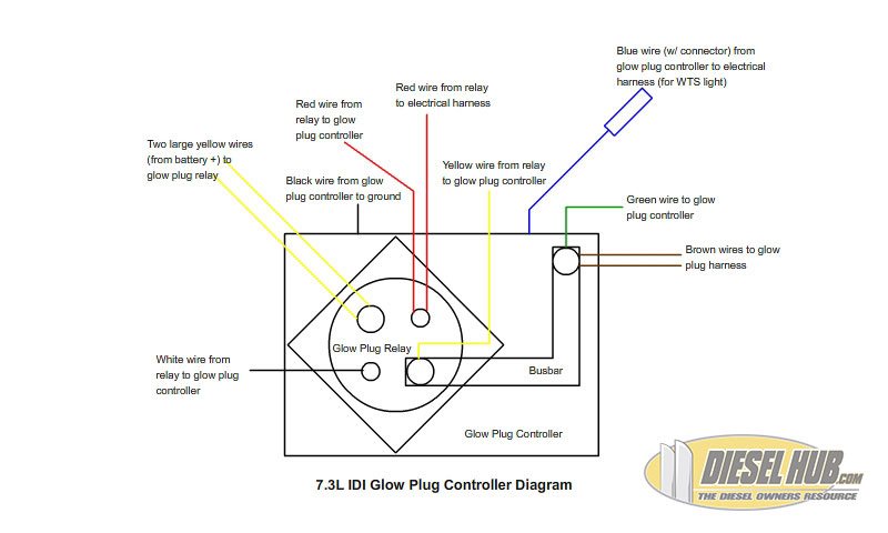
7.3L IDI Glow Plug Controller Operation
• When the key is turned to the "run" position, power is sent to the switching side of the glow plug relay (red wire, small terminal), energizing it and therefore completing the circuit between the batteries and the glow plug harness (two large yellow wires for the batteries, busbar to two large brown wires for the glow plug harness, large terminals on the relay). This also activates the wait-to-start indicator in the dash (blue/purple wire from the glow plug controller).
• As the temperature of the glow plugs increases, so does the resistance in the glow plug harness circuit. The glow plug controller, in effect, measures this resistance and breaks the ground to the switching side of the relay (white wire, small terminal) at a predetermined level of resistance (and therefore temperature of the glow plug itself). This protects the glow plugs from damage due to over use. The controller can be simply thought of as the glow plug timer.
• Positive power is applied to the switching side of the relay so long as the vehicle is running, but the glow plug controller breaks the ground as soon as the glow plugs have been heated and therefore the relay remains in the off position. Turning the key to the "off" position and then back to "run" will reset the controller and the glow plugs will repeat this cycle.
Glow Plug Wiring Diagram, Testing, & Troubleshooting
The glow plugs are located in the cylinder head, one for each cylinder. They stick out of the head about an inch, and are fed by a small brown wire with a bullet style electrical connector. The best way to test the glow plugs is to check the resistance in each one. To test the resistance in a glow plug with a digital multimeter, first disconnect the negative battery terminal from both batteries. Select the resistance setting of the multimeter (the settings on multimeters vary by model, but set your range for under 1k ohms). With the positive lead of the multimeter, probe the top of the glow plug. With the negative lead of the multimeter, probe the engine block at the base of the glow plug. The reading should not exceed 1 ohm. Most good glow plugs will read 0.1 to 0.5 ohms when resistance is checked (to provide a baseline, our testing indicated that a brand new Motorcraft glow plug had 0.3 ohms of resistance through it). Additionally, all 8 glow plugs should have relatively close resistance readings. If 7 glow plugs read 0.3 ohms of resistance and 1 glow plug reads 0.7 ohms of resistance, this is an indication that 1 glow plug is, at the very least, performing at a reduced capacity than the rest of the system. A single bad glow plug can cause the glow plug controller to malfunction. If you detect that 1 or more glow plugs is faulty, replace all 8; never replace a single glow plug, always change them in complete sets.
If the glow plugs have been tested and/or replaced, but the glow plug system is still not working, test the glow plug relay in this order:
• Make sure all connections to the relay are properly installed and secured. Look for burnt or corroded connections, clean as necessary.
• Check to make sure that the glow plug controller has a good ground; this is a common problem that will keep the relay from activating.
• With the batteries connected and the key in the "off" position, use a multimeter to make sure that the relay is receiving power. Set the multimeter to read voltage, probe the positive lead to the large terminal of the relay with two large yellow wires connected to it, and probe the negative lead to a good ground. You should read 12-14 volts if the batteries are good; this terminal on the relay is always hot. If power is not reaching the relay, the batteries are dead, the fusible links in the wiring harness have been compromised, or there is another problem in the wiring to the battery.
• With the key turned to the "run" position and both batteries connected, check voltage at the small terminal with 2 small red wires connected to it (positive lead to terminal, negative lead to good ground). 12 volts should be supplied to this terminal at all times that the key is in the "on" position. If no voltage is applied, the problem lies between the ignition switch and the relay.
• If the relay continuously clicks on and off when the key is turned to the "on" position, replace it. Relays have a finite life, and a new one is inexpensive
Fusible links are crimped into the 10 gauge yellow wires that supply battery power to the relay. A fusible link is an inexpensive fuse; when current is ran through the fusible link that exceeds its amperage limit, it physically burns, disconnecting the circuit. There are two 14 gauge fusible links in the glow plug system. From the glow plug relay, trace the two 10 gauge wires back to a large electrical connector. From the other side of the electrical connector, the two 10 gauge yellow wires will each have a 14 gauge fusible link spliced in. Splice in new fusible links of equal length and size if you suspect they have been burnt up.
The glow plug controller is the most expensive component of the system and is rarely the culprit. The best way to diagnose the controller itself is to test all other components first. If the problem is not the glow plugs or the glow plug relay, then by process of elimination it must be the glow plug controller. Always make sure that the controller has a good ground, or else neither the relay nor controller will function. The controller is grounded to the engine block, and it's relatively common for corrosion, oil, and contamination to weaken the strength of the ground over time. The terminal and mounting surface can be cleaned with some solvent and a small wire brush.
| Symptom | Common Cause(s) |
| Engine is hard to start when cold | If the glow plug relay/controller is working correctly but the engine is hard to start when cold, faulty glow plugs are the likely culprit. |
| Glow plug system cycles on and off rapidly (relay can be heard clicking on and off) | Bad relay, glow plug controller, or glow plugs - follow testing procedures above to solve problem. |
| Glow plug system does not activate (system does not turn on when key is switched to "run" position) | Bad ground to the glow plug controller, fusible links in the battery supply to the relay have burned up and need to be replaced, or a bad relay. Follow testing procedures outlined above to narrow possibilities. |
| Glow plugs turn on, but only briefly (accompanied by hard cold starts) | Bad glow plugs are the likely problem. If at least one glow plug is bad, the controller may be reacting to the higher resistance and switching the glow plugs off before they have time to reach ideal temperature. |
| Wait-to-start lamp stays illuminated or illuminates randomly when driving | Bad glow plug controller, the glow plugs are not likely being cycled, but the wait-to-start lamp is being activated by the controller. |
| Smell something burning or hear arcing when the glow plugs are activated | Check for loose, corroded, or burnt connections at the glow plug controller. Replace relay or clean terminals as necessary. |