6.0L Power Stroke IPR Valve Parts List
| Part Description | Part Number(s) | Remarks/Notes | |
| IPR valve | 2003 - early 2004 | Ford 3C3Z-9C968-AA | [1] |
| 2004 - 2007 | Ford 5C3Z-9C968-CA | ||
| IPR valve connector | Ford 6E7Z-12A690-DA | [2] | |
| IPR valve service kit | Ford 3C3Z-9H529-A | [3] | |
| IPR valve socket | OTC 6765 | [4] | |
| IPR valve controller | OTC 6764 | [5] | |
[1] Early and late 2004 models can be distinguished by ICP sensor location; if ICP sensor is located next to IPR valve through the HPOP cover, it is an early build 2004. If ICP sensor is located through the passenger side valve cover, it is a late build 2004.
[2] IPR valve connector is subjected to intense heat radiating off the turbocharger and thus should be inspected and replaced as required. Note that a faulty connector will emulate the symptoms of a failing/faulty IPR valve.
[3] Reseal kit for the IPR valve; Ford replacement IPR valve comes with these seals and they are only required if removing and reusing the IPR valve.
[4] Special socket required for IPR valve removal, features cut-away section to clear the connector protruding through the body of the valve.
[5]Diagnostic tool manually actuates IPR valve, not required for replacement.
IPR Valve Function, Diagnostics, & Troubleshooting
The IPR (injection pressure regulator) valve is responsible for regulating oil pressure in the high pressure oil circuit. Recall that the 6.0L Power Stroke, like its predecessor, relies on an electronically controlled hydraulic injection system in lieu of a high pressure injection pump. In this system, injection pressure is dictated by the oil pressure produced by the high pressure oil pump and supplied to each individual injector. Oil pressure in this circuit can exceed 3,000 psi at full load and produce injection pressures up to 26,000 psi. It is the task of the IPR valve to regulate this oil pressure, which must maintain a minimum 500 psi for an injector to operate. If oil pressure drops below 500 psi, a fuel injector will not be commanded to fire by the FICM (fuel injection control module).
The IPR valve is located in the output circuit of the high pressure oil pump (HPOP). The IPR valve is commanded closed to build pressure and open to bleed off pressure to the crankcase. The IPR valve is therefore perpetually altering its position (duty cycle) to maintain an ideal oil pressure for the current operating parameters (engine load, speed, etc). The position of the IPR valve depends on the duty cycle being commanded, where 15% is fully open and 85% is fully closed.
A failed/failing IPR valve and/or IPR valve connector can result in a hard start, no start, rough running, or stall condition. Verifying IPR valve function is not particularly difficult with a scantool that has the ability to read the IPR and ICP PIDs (parameter IDs); even some aftermarket tuners/programmers feature this functionality. While monitoring the "injector control pressure", "injector control pressure desired", and "injector pressure regulator duty cycle" PIDs, verify the following:
| PID | Value, Engine Cranking | Value, Engine Idling | Notes |
| ICP | minimum 500 psi | 600 - 800 psi | Typically between 800 and 2,000 psi before engine starts; if ICP does not build this high while cranking, IPR is likely bleeding off pressure when it should not be. Normal ICP at idle is 600 to 800 psi. |
| ICP desired | --- | --- | Value should be reasonably close to actual ICP; if values are far off, IPR valve could be failing to regulate oil pressure properly, or the ICP sensor could be malfunctioning. |
| IPR duty cycle | up to 84% | ~ 30% | IPR duty cycle should start at 15% with the key "ON" and engine "OFF". While cranking, IPR duty cycle should rapidly increase to near peak (85%) until engine starts or ICP reaches ~ 2,000 psi. If IPR duty cycle is significantly greater than 30% at idle, there is likely a leak in the high pressure oil system. The minimum IPR duty cycle is 15% (fully open); the maximum duty cycle is 85% (fully closed). |
If IPR duty cycle does not move from 15% while cranking, the IPR has lost connection or failed as this is its default position. An external controller can be used (OTC Tools 6764) to manually command the IPR valve duty cycle in the event of a no start condition. While this is a powerful tool, process of elimination remains necessary to ensure that the IPR valve is the culprit. A bad ICP sensor can cause similar problems, and a faulty ICP reading may direct the IPR valve to operate erratically.
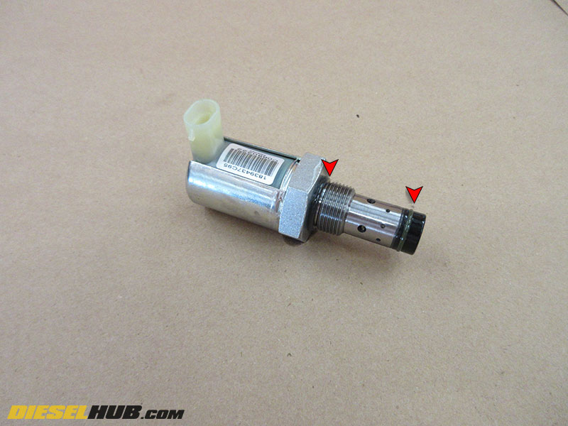
IPR valves that have an external leak can be repaired using Ford service kit 3C3Z-9H529-A to replace the o-rings and mesh screen on the nose of the valve.

How to Remove & Replace the IPR Valve on a 6.0L Power Stroke
Click any thumbnail to view fullsize, detailed image
• Disconnect both negative battery cables.
• Drain approximately 3 gallons of engine coolant from the radiator into clean containers so that it can be reused. The drain valve is located on the bottom of the radiator on the driver side.
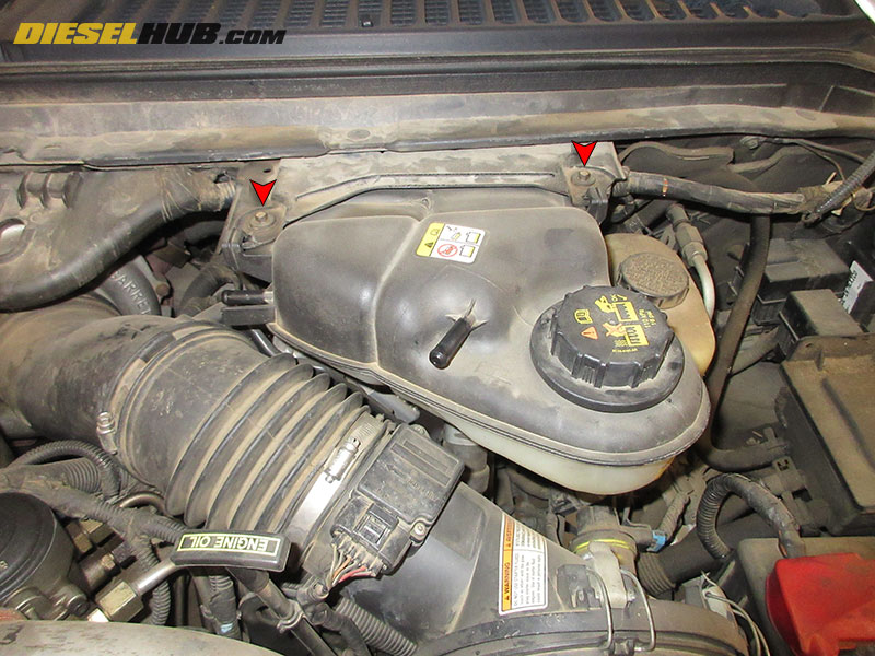
• Disconnect the (2) coolant lines attached at the top of the degas tank and the (1) large coolant hose attached at the bottom.
• Remove the (2) bolts securing the degas tank with an 8 mm socket, then remove the tank and set aside.
• Remove the intake tubing from the turbocharger inlet to the air filter.
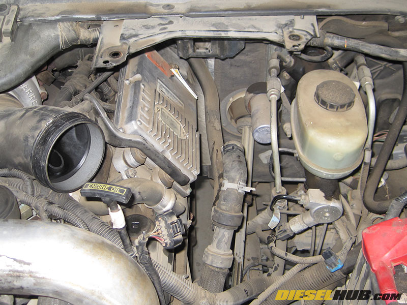
• Remove the FICM and FICM mounting bracket (if necessary, see 6.0L Power Stroke FICM removal for specific instructions).
• Remove the ground from the rearmost intake manifold stud on the driver side (small ring terminal).
• Remove each fuel injector connector on the driver side bank (push metal clip into connector then pull up, or remove the metal clip altogether and pull up).
• Remove the rearmost intake manifold bolt with a 10 mm deep socket (where ground terminal was previously connected). This will make it significantly easier to reach the IPR valve.
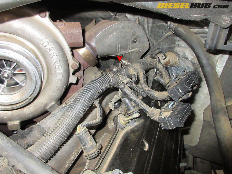
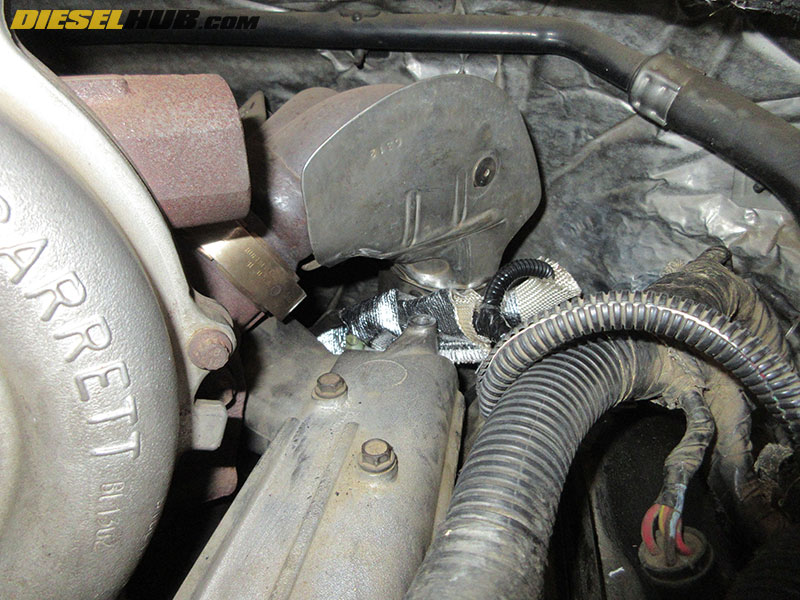
• Reach under the turbocharger up-pipe collector and unplug the IPR valve and ICP sensor connectors (if applicable, ICP is located next to IPR on 2003 and early 2004 model year engines).
• Pull the entire driver side electrical harness toward the front of the engine out of the way. There may be several locations where the connector attaches to the valve cover using small snap clips.
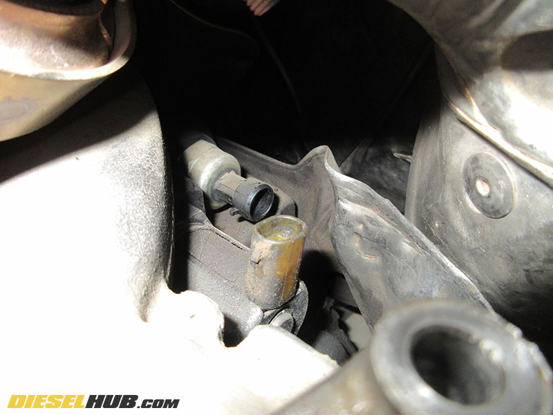
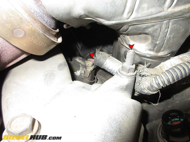
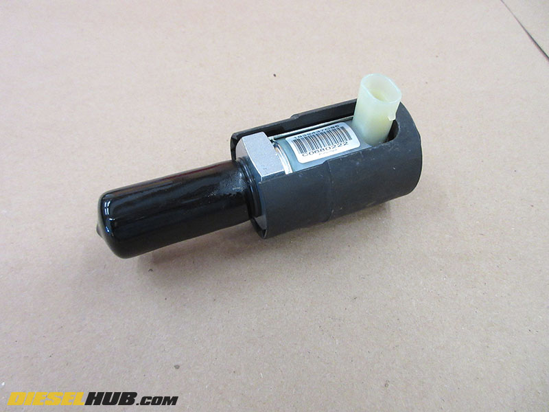
• Locate the IPR valve. It is attached through the high pressure oil pump cover plate at the rear of the engine beneath the turbocharger up-pipe collector/turbine inlet. It has a 90 degree connector that points upwards towards the hood. On 2003 and early 2004 model years, do not confuse it with the ICP sensor, which is located closest to the firewall.
• A special socket (OTC 6765) is required to remove and install the IPR valve as it has a large slot machined down one side that allows it to slide over the valve body without interfering with the connector.

• Remove the IPR valve using an appropriate socket. Access is limited; a 3/8" drive socket wrench with a flexible head is recommended and makes quick work of removing the IPR valve.
• Liberally coat the o-rings on the replacement IPR valve with clean motor oil to ensure a positive seal.
• Reinstallation of the IPR valve is in reverse order; torque to 37 lb-ft.
Recommended - see connector replacement below before reinstalling the FICM, etc.
6.0L Power Stroke IPR Valve Connector Replacement
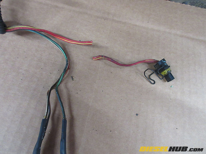
• The connector should be labeled "A" and "B" on either side of the shell/housing. Identify which wire color corresponds to each terminal and make a note. Verify that the "A" and "B" positions on the replacement connector correspond to the same positions on the replacement connector.
• Use the length of the replacement connector pigtail to determine how much of the factory harness to remove (i.e. don't cut 8 inches out of the wiring harness if the replacement pigtail is only 4 inches in length).
Note - If the connector has been replaced previously and you are cutting the old pigtail off directly after the splice point or you are unable to read the "A" and "B" markings on the side of the connector shell, you may need to label the wires above and below the point at which you intend to cut the wires. Then, the features of the connector (the nose of the connector is not symmetrical in both planes) can be used to match the appropriate wire to the correct terminal position on the new connector.
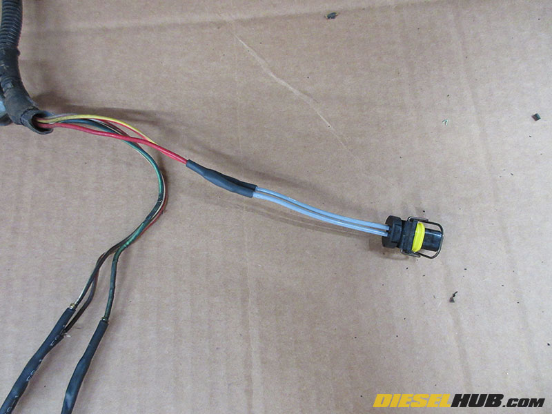
• Splice in the new connector pigtail, verifying that the correct wire is spliced into the correct terminal position on the replacement connector.
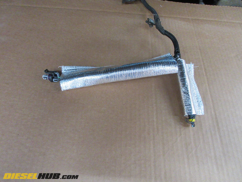
• Repair the factory wire loom and heat shielding as necessary. Here, we've removed and replaced ~ 6 inches of the factory 1/4 inch plastic loom that was damaged. Then, fiberglass sleeving was installed over both the IPR valve and ICP sensor wires. Finally, a fiberglass sheath with a radiant heat barrier was installed over the sections of wire that are exposed to the heat of the turbocharger up-pipe.
• Reinstall the wiring harness. We've slid our radiant heat barrier over the ICP sensor and IPR valve connectors to protect them from the heat produced by the turbocharger and up-pipes and hopefully prolong there service life.
