6.2L & 6.5L GM Diesel Glow Plug Controller Operation
6.2L/6.5L Diesel Glow Plug Controller Part Numbers
| Part Description | Part Number(s) | Remarks/Notes |
| Glow plug controller, 1985 - 1993 models | ACDelco 212-367 Airtex/Wells 1R1332 |
--- |
| Glow plug controller, 1994+ models | ACDelco 212-366 Airtex/Wells 1R1372 |
--- |
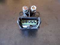
Glow plug cycle time is dependent on engine coolant temperature. On pre-1994 model engines, a glow plug inhibit switch disables the glow plug system if the coolant temperature exceeds 125 °F. On 1994 and newer engines, the ECM will initiate the glow plugs for a predetermined period of time based on engine coolant temperature. The WTS light will be illuminated anytime the glow plug system is activated, including during any post-heat cycles. The glow plug controller for all 1992 - 1993 engines and 1994+ non-electronic (fully mechanical injection pump, no electronic pump mounted driver) engines uses a 4 pin connector. All 1994+ engines with an electronic injection system (electronic pump mounted driver) use a 3 pin glow plug controller. You can verify your controller type by simply pulling the electrical connector off and counting the male pins. The following procedures are applicable to all 1985+ 6.2L and 6.5L GM diesels. For a complete list of glow plug system diagnostics and troubleshooting strategies, see: 6.2L & 6.5L GM diesel glow plug system troubleshooting.
The following procedures are based on a 6.5L turbocharged engine. The steps are identical for 6.2L and naturally aspirated 6.5L engines, however there are subtle differences (such as the absence of a wastegate solenoid).
How To Replace the Glow Plug Controller on a 6.5 GM Diesel
Click any thumbnail to view high resolution, fullsize image w/ details
• Disconnect both negative battery cables.
• Remove the plastic "Turbo Power" engine cover (if applicable).
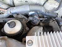
• Locate the glow plug controller on the driver side, rear of the engine. It is mounted to the right of and behind the fuel filter housing on a bracket near the firewall.
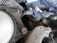
• Remove the positive input and output terminals with a 13 mm socket.
• The glow plug controller studs are shared with the wastegate solenoid. Remove the nuts from both glow plug controller studs and the third nut holding down the wastegate solenoid bracket. A 15 mm socket is required.
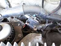
• Gently remove the wastegate solenoid bracket from the mounting studs and push it aside without putting any strain on the lines/harness.
• Lift the glow plug controller off of the mounting studs and carefully rotate it until the connector release is accessible. Do not put any strain on the connector wires/harness.
• Pull the blue safety/retaining clip from the connector (if applicable), then release and remove the connector from the glow plug controller.
• Install the glow plug controller in reverse. Use dielectric grease on the connector pins and input/output lugs.
• Reconnect the negative battery cables and test for proper glow plug operation.


