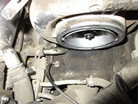
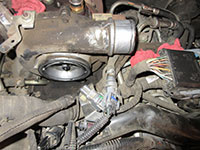
The 6.6L Duramax LLY, LBZ, LMM, and LML engines utilize a Garrett GT3788VA variable geometry turbocharger (VGT); this type of turbo is sometimes also referred to as a variable vane turbocharger (VVT). For these 2004 to 2016 model year engines, the turbocharger is mounted in the engine valley at the rear of the engine, thus there are significant spacial constraints to overcome in accessing various components. Although removing the turbo on these Duramax diesels is somewhat of a cumbersome task, the entire process is outlined in great detail below.
One of the most common reasons that dictates removal of the turbocharger on these engines is a non-functioning or mechanically seized unison ring. The unison ring is integral to the position of the vanes in the variable geometry design and it changes their pitch as it is rotated by the VGT solenoid and actuator assemblies. Soot has a tendency to build up between the various mating surfaces in the turbine housing, impeding movement of the associated components before eventually seizing entirely. The only remedy for such conditions is to remove the turbocharger from the engine, disassemble it, and thoroughly clean the components manually.
Turbo Removal and Installation Parts List
| Part Description | Part Number(s) | Remarks |
| Oil filter | ACDelco PF2232F | [1] |
| Engine coolant | ACDelco DEX-Cool (GM 12346290) | [2] |
| CCV/PCV hose o-ring | GM 94420097 | Qty (2) req |
| Turbo oil supply line crush washer | GM 97331137 | Qty (2) req |
| Turbo oil drain tube gasket, upper | GM 97227012 | Qty (1) req |
| Turbo oil drain tube gasket, lower | GM 97208191 | Qty (1) req |
| Turbo coolant line crush washer | GM 97373522 | Qty (2) req |
| Up-pipe to turbocharger flange gasket | GM 97192618 | Qty (2) req |
| Up-pipe to exhaust manifold flange gasket | GM 97188685 | Qty (2) req |
| Up-pipe bolts | ARP 672-1003 | [3] |
| Turbo oil supply line | GM 97374369 | [4] |
| Turbo oil drain line | GM 97303638 | |
| Turbo coolant inlet hose | ~ 3.5" of 3/8" ID heater hose/coolant line | [5] |
| Turbo coolant outlet hose (elbow) | GM 97383472 | [6] |
[1] - Engine oil and lube oil filter must be changed after the turbocharger has been reinstalled.
[2] - Engine coolant can be collected in clean containers and reused if not contaminated. OEM orange DEX-COOL coolant listed.
[3] - Up-pipe and turbocharger hardware should not be reused because it is subjected to frequent heating and cooling cycles, occasionally reaching extremely high temperatures. Over time, the material properties of these components will deteriorate; failure of re-used hardware is likely.
[4] - Turbocharger oil supply and drain lines can be reused if not damaged, bent, or kinked.
[5] - Smaller diameter coolant hose on drivers side of turbocharger; replacement is optional, can be reused at the discretion of the installer.
[6] - Larger diameter coolant hose with 90 degree bend on passenger side of turbocharger; replacement is optional, can be reused at the discretion of the installer.
How to Remove the Turbocharger on a 2004 to 2016 Duramax Diesel
Click any thumbnail to view fullsize, detailed image
• Disconnect both negative battery cables.
• Remove the passenger and driver side inner fenders (series of plastic clips).
• Secure the front of the vehicle on appropriately rated jack stands and remove both front tires.
• Drain the radiator into a clean container so that it may be reused (easiest method is to pull the lower radiator hose through the passenger side inner fender).
• Remove the section of intake tubing between the air filter box and the turbocharger compressor inlet mouthpiece.
• Remove the intake resonator.
• Loosen the clamp for the crankcase ventilation coupler (connects left and right CCV tubes to intake tubing at compressor inlet mouthpiece).
• Remove the driver side intercooler tube (hot side). It will need to be maneuvered out through the driver side fender; be cautious not to snag any of the various electrical harness components. The intercooler boot clamps require an 11 mm deep socket.
• Trace the CCV hose to the passenger side valve cover. Remove the 8 mm bolt securing the hose retainer to the valve cover fitting. Gently rotate the hose left-to-right while pulling upwards to remove it from the valve cover fitting.
• Repeat for the driver side CCV hose (it is a mirror image of the passenger side, albeit with less room to work).
• Remove the CCV coupler from the intake tube at the turbocharger inlet and set the hose assembly aside.
• Disconnect the glow plug controller connectors (driver side of turbocharger near firewall). The left connector has two knurled tabs 180 degrees apart; press the tabs, then pull out the connector. The right connector has a retainer that slides towards the driver side, then the connector can be pulled out.
• Remove the glow plug controller with a 10 mm socket (2 bolts).
• Remove the glow plug controller heat shield. (4) bolts require a 12 mm socket and the single bolt at the fuel line requires a 10 mm socket.
• Remove the glow plug controller bracket with a 12 mm socket. There are (2) bolts at the front of the bracket and (1) hidden behind the foot of the bracket. The rear bolt will require a box end wrench as a socket will not fit.
Remove the (3) bolts securing the heat shield to the top of the turbocharger with a 10 mm socket. Bend and/or cut the heat shield as necessary to remove it from the engine compartment. It CANNOT be removed without bending or cutting; it is common to cut the corner off the shield on the passenger side to allow for easy removal and installation.
• Disconnect the electrical connector for the vane position sensor and maneuver it through the wiring harness. Remove the protective heat shield by cutting the band clamp around the sensor. Finally, remove the vane position sensor (a special socket, such as Schley SCH12400, is required to remove the sensor).
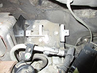
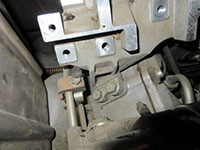
• Locate the transmission dipstick tube bracket behind the turbo downpipe. Loosen the (2) nuts with a 13 mm socket/wrench. Once loose, pull the bracket up and over the bolts so that the dipstick tube and bracket float freely. The bracket is slotted such that the nuts do not need to be removed entirely, just loosened.
• Remove the (3) bolts securing the downpipe heat shield using a 10 mm socket. Pull the heat shield out from behind the turbocharger; it will not fit past the frame rail if you attempt to remove through the fender.
• Loosen, then remove the Marman clamp securing the downpipe to the turbocharger turbine outlet with a 12 mm deep socket. Using a 11 mm deep socket, remove the Marman clamp securing the downpipe to the exhaust pipe.
• Remove the bracket securing the downpipe to the passenger side exhaust manifold using a 14 mm socket.
• Remove the downpipe, maneuvering it through the hood (it will not fit through the fender opening). These tend to be stubborn; rotate the downpipe up and down to free it from the turbine outlet. Have patience, it will come out from behind the turbo.
• Remove the driver side up-pipe heat shield; it is secured with (4) bolts requiring a 10 mm socket. You will need to feel for the bolts as space is limited and you will not physically be able to see all of them.
• Remove the driver and passenger side up-pipes from the turbocharger turbine housing inlet. There are (3) bolts per up-pipe, all requiring a 12 point, 12 mm socket. The head of the bolts can only be removed with a 12 point socket.
These bolts are extremely stubborn. The best method of accessing them is through the passenger side inner fender. Use a large breaker bar to break them loose while a helper holds the socket on the bolt. Do not be surprised if 1 or more of the bolts breaks. You may find it useful to soak the bolts in penetrating oil overnight before attempting.
• Remove the driver side up-pipe from the exhaust manifold using a 12 point, 12 mm socket. Again, this is easier with two people as space is limited and you do NOT want to strip the head of one of these bolts as they are difficult to extract. Let the up-pipe float in place, it only needs to be moved to access the oil drain line.
• Remove the (2) bolts securing the oil drain tube to the engine block with a 12 mm socket.
• If desired, the oil drain tube can be removed altogether by first locating and removing the bolts beneath the turbocharger center section (bearing cartridge). This is optional, as the turbocharger can be removed from the vehicle with the drain tube still attached to the underside of the bearing cartridge.
• Remove the oil feed line banjo bolt and sealing washers from the top of the turbocharger using a 14 mm socket.
• Remove the VGT solenoid (actuator) using a 12 point, 8 mm socket. The bolt is located at the bottom of the bracket.
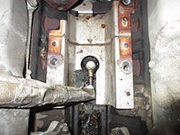
• The turbocharger pedestal is secured to the engine block using (3) bolts, all requiring a 17 mm socket. The bolt on the passenger side is easily accessible.
• The front most pedestal bolt on the driver side is extremely difficult to see, let alone reach. You will need to use a swivel socket or universal swivel joint and a series of extensions to reach the bolt. See full-size image for bolt location details.
The pedestal bolts can be stubborn and you may need a breaker bar to apply enough force to break them loose.
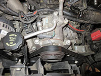
• Use a 1/2 drive belt tensioner tool to relieve the belt tensioner, then slide the serpentine belt off of the AC compressor; it does not need to be removed entirely.
• Disconnect the (2) electrical connectors from the AC compressor.
• Remove the (4) bolts securing the AC compressor to its bracket using a 15 mm socket/wrench.
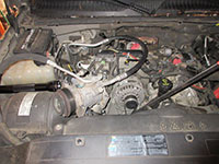
• Carefully move the AC compressor out of the way, letting it rest between the alternator and the air filter box. Do NOT kink the AC lines; refer to image for clarification.
• Disconnect the turbo coolant outlet line (90 degree hose towards passenger side of compressor housing). This line is typically brittle and may be difficult to remove; it can be cut and replaced.
• Disconnect the turbo coolant inlet line (driver side of compressor housing). This line is typically brittle and may be difficult to remove; it can be cut and replaced.
• Maneuver the turbocharger out of the vehicle. This is much easier with two people, as one person can monitor the oil drain tube to ensure it does not become entangled with another component. While it is a tight squeeze, it WILL come out!
• With the turbocharger removed from the engine, remove the oil feed line with a 14 mm socket so that the sealing washer can be replaced prior to reinstallation.
Turbocharger Installation
Reinstallation of the turbocharger is precisely reverse of removal. All gasket mating surfaces must be thoroughly cleaned prior to reinstallation of any applicable part. Gaskets and sealing (crush) washers should not be reused under any circumstances; refer to parts list above for part numbers. All necessary torque specifications are listed in the chart below; note that any component that touches the exhaust manifold, up-pipes, or turbine housing may need to be re-torqued after completing several drive cycles.
Once the turbocharger has been reinstalled, the journal bearings must be pre-lubed before attaching the oil feed line. To do so, add approximately 100 to 200 milliliters of new engine oil into the oil supply line hole at the top of the turbocharger bearing housing while rotating the compressor wheel by hand. Failure to pre-lube the bearings may result in excessive wear or damage when the engine is first started as the bearings will run dry. This is particularly true if you are installing a new or recently rebuilt turbo.
Torque Specs For Turbocharger Installation
Component(s) |
Torque Spec, in-lbs |
Torque Spec, ft-lbs |
AC compressor |
--- |
37 ft-lbs |
Turbocharger oil supply banjo bolts |
--- |
19 ft-lbs |
Turbocharger oil drain tube nuts |
89 in-lbs |
--- |
Up-pipe to exhaust manifold flange bolts |
--- |
39 ft-lbs |
Up-pipe to turbocharger flange bolts |
--- |
39 ft-lbs |
Turbocharger pedestal bolts |
--- |
80 ft-lbs |
Turbocharger heat shield |
89 in-lbs |
--- |
Turbocharger coolant line banjo bolts |
--- |
19 ft-lbs |
Intercooler boots |
71 in-lbs |
--- |
Glow plug controller |
89 in-lbs |
--- |
Glow plug controller bracket |
89 in-lbs |
--- |
Downpipe bracket nut |
--- |
39 ft-lbs |
Downpipe clamp |
--- |
11 ft-lbs |
Downpipe to exhaust system clamp |
--- |
11 ft-lbs |
CCV/PCV tube bolts |
35 in-lbs |
--- |


