Overhead Display Module Repair Parts List
| Part Description | Part Number(s) | Remarks/Notes |
| Overhead display module (cabs w/o sunroof) | Ford 3C3Z-10D898-AA | --- |
| Overhead display module (cabs w/ sunroof) | Ford 3C3Z-10D898-BA | --- |
| Overhead display trim piece | Ford 2C3Z-25519A70-AAC | [1] |
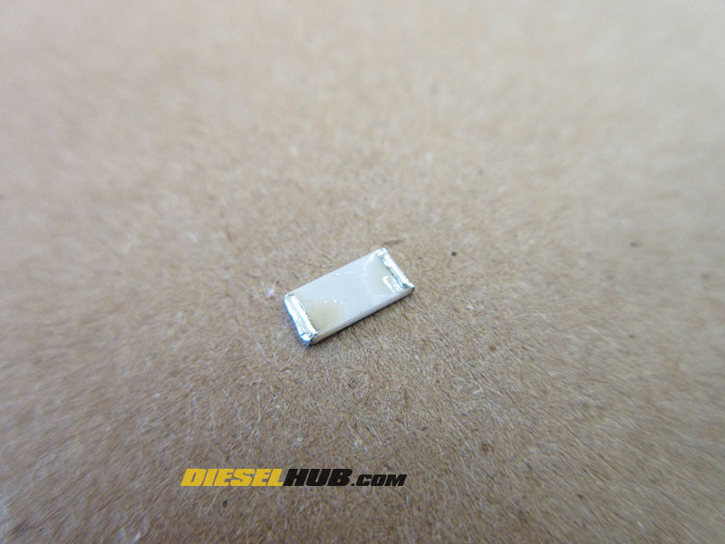
| 62 Ω thick film chip resistor | Panasonic ERJ-S1TF62R0U | [2] |
| 68 Ω thick film chip resistor | Panasonic ERJ-1TNF68R0U |
[1] Trim piece tends to get brittle and crack during removal, but replacement parts are readily available.
[2]Any 1 Watt, 1% tolerance thick film resistor will suffice; Panasonic versions readily available and easy enough to find.
Overhead Display Module Resistor Failures
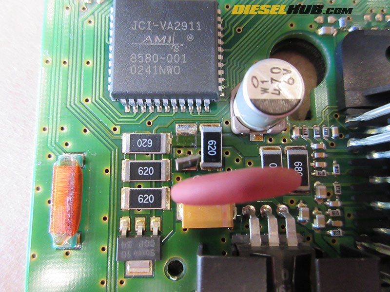
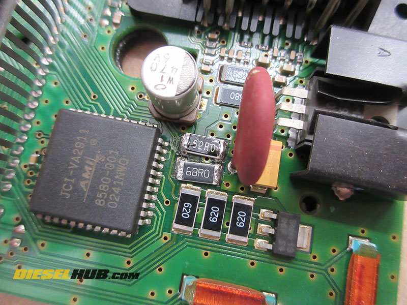
The most common cause of overhead module failures is a broken solder joint at one or more resistors on the PCB (printed circuit board). This is either due to a resistor being improperly soldered (i.e. cold soldered) or soldered with an inadequate amount of material from the factory. In the figure below, you can clearly see that a resistor has been jarred loose and is completely disconnected at one end. An adjacent resistor has a large crack in the solder joint and has also begun to move.

A typical repair service will charge $100 - $150 to repair this module or exchange it for a repaired unit while a brand new replacement from Ford can cost several hundred dollars. The repair, however, cost about $1.00 per resistor that needs to be replaced. The resistors used are known as thick film chip resistors, and there are two different sizes used; 62 and 68 Ohm resistors, both of which have a 1 Watt rating. "Ohms" is the standard unit of resistance and is often denoted by the Greek letter Omega (Ω). 62 Ω resistors mounted to the PCB are labeled "620" while 68 Ω resistors are labeled "680". The replacement resistors may be labeled differently, or not at all. Their resistance can be and should be confirmed with a multimeter prior to installation.
When selecting resistors you will also need to look at the tolerance, which will be listed as a percentage of deviation from the listed resistance specification. For example, a 62 Ω resistor with a 1% tolerance will measure between 61.38 and 62.62 Ohms of resistance, whereas the same resistor with a 5 % tolerance will measure between 58.90 and 65.10 Ohms of resistance. Smaller tolerances thus denote a more reliable and precise resistance rating.
Basic hand tools and a soldering iron are all that's required to repair overhead modules that have one or more broken resistors. You don't have to be an expert at soldering to perform this repair, but the following procedures assume that you understand the fundamentals. Although we recommend replacing resistors that are found loose, broken, etc, they can simply be reattached if they are not damaged. A quick Ohm test with a multimeter will identify whether or not a resistor is bad.
Ford Super Duty Overhead Display Module Resistor Repair Procedures
Click any thumbnail to view fullsize, detailed image
• Disconnect both negative battery cables to disable power to the vehicle.
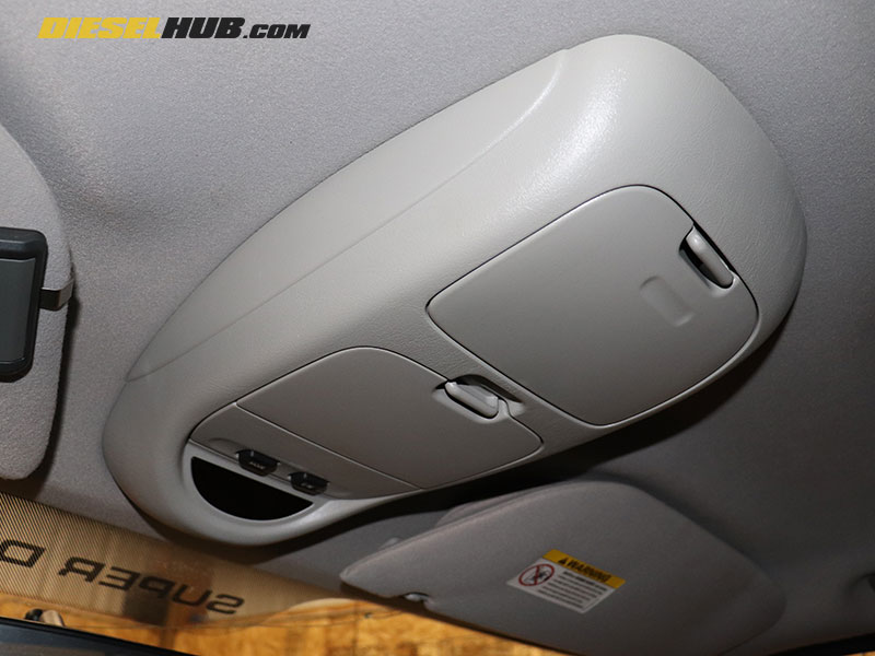
• Remove the trim panel/overhead organizer to gain access to the overhead module. Begin by prying at the front or back and working around the perimeter of the panel. (4) clips secure the trim piece in place and they are fairly sturdy.
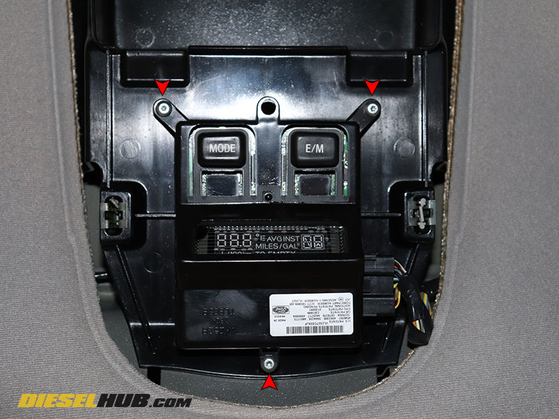
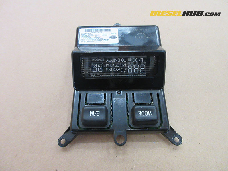
• Remove the (3) T10 Torx screws securing the overhead module to the headliner bracket, then carefully unplug the electrical connector to remove it from the vehicle.
• Place the module on a clean workbench and remember that many of the electronics are delicate and easy to damage.
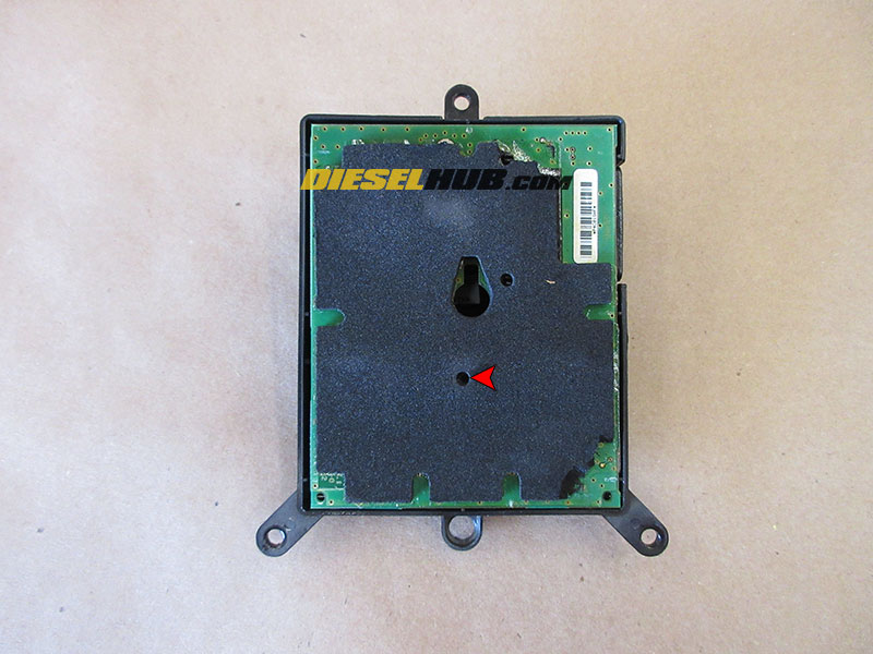
• On the backside of the module, locate the single screw that secures the cover to the circuit board; it will be hidden by insulation, so you will have to carefully search for it and expose it through the insulation (use image for reference).
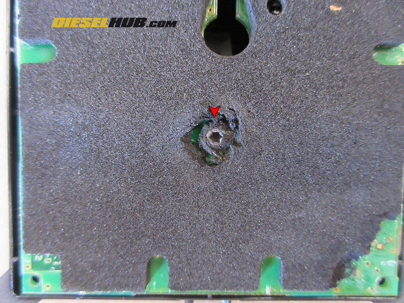
• Once exposed, remove the screw securing the cover to the circuit board with a T10 Torx driver.

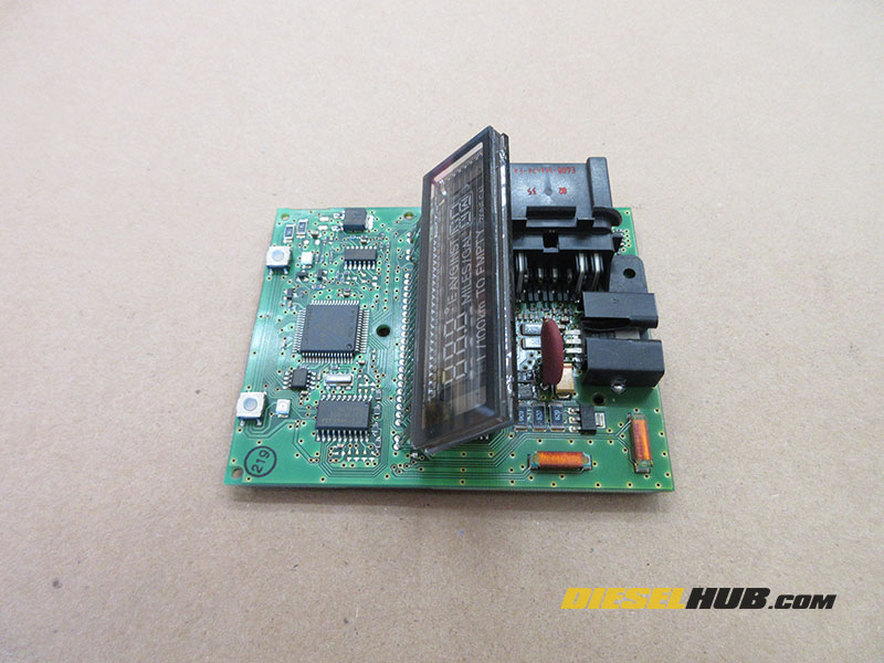
• Carefully separate the black cover from the circuit board.
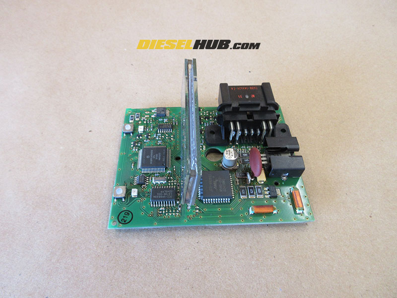
• Carefully pry the LCD display upwards so that it is perpendicular to the circuit board; this will improve access to the series of resistors beneath it.

• Locate the problem resistor(s); this one is blatantly obvious, as one of the resistors is standing upright.
• If more than one resistor is damaged, note the location and sizes.
• Remove the faulty resistor(s); you may need to apply heat with a soldering iron to remove.
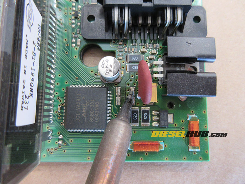
• Use a soldering iron and clean piece of stranded copper wire (18 -22 AWG) to desolder the old resistor joints as much as possible. Preheat the copper wire with the soldering iron and apply a small amount of flux, then touch the solder joint with the copper wire and soldering iron. Once the solder wicks up the copper wire pull it away, then remove the soldering iron. Repeat for all necessary connection points.
• With the resistor upside down, apply a small amount of solder to each connection joint; this will make the resistor much easier to install. If you are not using a rosin cored solder, you should be using an appropriate solder flux.
• Orient the resistor appropriately and solder in place; only a small amount of solder should be necessary.
• If you find a resistor installed crooked, reheat the connection and carefully push it into the appropriate position with a pick, tweezers, etc. Remove the soldering iron and hold it in position until the solder solidifies, then solder the adjacent connection.
• Once the appropriate resistor(s) have been replaced/repaired, carefully bend the LCD screen back into its original position.
• Reinstall the plastic cover over the PCB; do not overtighten.

• Reconnect and reinstall the module; do not overtighten the Torx screws as the mounting tabs are easy to break.
• Reinstall the trim piece, reconnect the negative battery cables, and test for proper operation.
