Applicable Models:
1983 - 1994 Ford F-250, F-350 trucks
1983 - 1993 Ford E-250, E-350 vans
1988 - 1994 F-Super Duty trucks
Applicable Engine(s):
International 6.9L IDI V-8
International 7.3L IDI V-8
7.3 IDI Fuel System Overview
The 6.9L and 7.3L IDI diesels employ a simple mechanical fuel system with the exception of an electromechanical actuator mounted to the injection pump that controls the fuel metering valve. When this actuator is energized, fuel flows freely into the injection pump and when the actuator is de-energized fuel flow is cut off. Fuel is drawn from the fuel tank by a diaphragm type fuel pump mounted towards the front, passenger side of the engine block. This low pressure fuel pump, also sometimes referred to as a lift pump, supply pump or transfer pump, is driven by a lobe attached to the front of the camshaft. The lift pump operates at very low pressures (> 5 psi) and its purpose is to maintain a steady flow of fuel to the injection pump.
The IDI's fuel filtration system is mounted between the lift and injection pumps. Fuel from the tank to the lift pump is unfiltered, although it must flow through a mesh strainer mounted to the foot of the in-tank sending unit. Fuel from the lift pump is pushed through a spin-on fuel filter before being delivered to the engine mounted injection pump. The injection pump's integral transfer pump ramps up the fuel pressure, internally, to 60 to 120 psi. At its final stages, fuel injection pressure (as delivered to the fuel injectors) ranges between 1,425 and 1,950 psi. Fuel flow through the injection pump lubricates and cools the internal components. All 6.9L and 7.3L IDI diesels utilize a Stanadyne DB2 rotary type injection pump.
A fuel-water separator, water-in-fuel sensor, and drain valve are incorporated into the bowl of the fuel filter on 7.3L IDI diesels, but not 6.9L IDI diesels; 6.9L diesels have a standalone fuel-water separator mounted on the firewall near the brake booster. Most IDI's we see have ditched the filter mounted water separator in favor of a simpler canister type filter with a water separator/drain valve incorporated into the base of the filter. This is a significantly simpler setup that is less prone to leaks. A vacuum switch mounted atop the filter mount serves as a fuel restriction sensor. Excessive vacuum causes the switch to close, illuminating the fuel restriction indicator light in the dash.
Testing Fuel Pressure
Fuel pressure is tested at the Shrader valve port installed into the fuel filter mount. This fitting is also referred to as the fuel priming valve in some service texts, as this port was used to bleed air from the fuel system following initial production. Testing fuel pressure at this port requires a Ford type fuel port adapter (Ford schrader valve adapter OTC 0180-1280), which is a fairly common adapter in fuel test equipment sets. You may also choose to update to the more common 1/4 inch flare adapter, part number DP-160401.

Simply secure the fuel pressure test gauge hose to the appropriate fitting on the fuel filter mount (see figure 1 above, updated 1/4 inch flare adapter shown) and crank/start the engine to read fuel pressure. If there is leakage at the port, stop the test and tighten the fittings. A small increment test gauge with a 0 to 10 psi range is ideal for measuring fuel pressure on the 6.9L and 7.3L IDI diesels because their fuel pressure output from the lift pump is relatively low. Gauges with greater ranges, 0 to 100 psi, for example, have a difficult time registering fuel pressures less than 5 psi and thus your readings will not be terribly accurate and the test may be misrepresented.

Another consideration in gauge type is liquid filled vs dry. In systems with a mechanically driven fuel pump, such as the 6.9L and 7.3L IDI, liquid filled gauges help to reduce the oscillation (bouncing) of the pointer in relation to the pulsing of the fuel pump. While electric fuel pumps produce relatively constant pressure and flow, the IDI's fuel pump is driven once per complete rotation of the camshaft, thus the pressure pulses considerably more. This can cause the pointer on dry gauges to bounce rapidly in-tune with these pulsations, while the liquid filled gauge's pointer will produce a more stable reading (albeit with some movement).
Pressure Specification
Fuel pressure should register a minimum 2 psi at idle and 1 psi at 3,000 rpm. However, it is more common for a healthy fuel system (clean filter, new pump, etc) to produce between 4 and 5 psi at idle. Since the engine idles at approximately 675 rpm but rotates at a quarter of this speed during starting, low lift pump supply pressures may be acceptable when testing while engine cranking. If engine registers positive pressure and flow while cranking but will not start, the fuel pump may not be the culprit but is worth re-testing once the engine is able to be started. No fuel pressure while cranking the engine indicates the engine is likely not receiving fuel from the tank.

Fuel flow, also tested through the Shrader valve port, should produce at least 1 pint of fuel every 30 seconds at idle. If the engine dies while performing this test, the lift pump is not supplying enough fuel due to a fuel pump issue or fuel system restriction. When performing the fuel flow test, inspect the retrieved fuel for contamination. Diesel fuel should be generally clear and not cloudy. Dark, cloudy, or water contaminated fuel needs to be removed and disposed of before it causes additional fuel system damage or corrosion.
Symptoms of a Bad Fuel Pump
Poor fuel pressure or flow, the later of which is more likely on this engine platform, can cause a number of symptoms that include:
- No start, hard start, long crank condition due to poor, restricted, or no fuel flow
- Rough idle, engine misfire, bucking under load, may not run at higher engine speeds or under load
- Low performance, especially at higher engine speeds and load
It is noteworthy that these symptoms do not immediately identify the fuel lift pump as the culprit. Low fuel pressure or flow can also be caused by a plugged fuel filter or other fuel system restriction, including plugging of the in-tank fuel strainers. Although these strainers are a coarse mesh, certain fuels and/or fuel storage conditions can cause corrosion and contamination inside the fuel tank. Always perform a visual fuel quality inspection when diagnosing fuel system related concerns.
Fuel System Priming
It will take significant crank/run time to completely prime the fuel system and clear it of air after replacing the fuel lift pump or opening any of the fuel supply lines. The fuel filter should be primed with clean fuel poured through the small openings of the filter assembly. Do not pour fuel into the large center hole of the filter assembly. This is the outlet side of the filter where filtered fuel is delivered to the injection pump. Fuel that is poured into the center hole will travel to the injection pump unfiltered. We also highly recommend adding a healthy dose of lubricating fuel additive to the fuel filter. This will ensure that the injection pump and fuel injectors are well lubricated during the priming period, and will help prevent excessive wear while these components are purging air from the system.
Excessive engine cranking will drain the vehicle batteries and may overheat the starter motor. Excessive glow plug cycling may also cause damage to one or more glow plugs. Only crank the engine for 7 to 10 seconds at a time followed by a 2 minute cool-down and connect a battery charger to one of the vehicle batteries.
If the system fails to prime after 4 to 5 attempts, disable the glow plug system by removing the white wire from the front-most, small terminal on the glow plug relay (on a 6.9L IDI, simply remove the connector from the controller). This will prevent the glow plugs from cycling as well as prolong battery life while attempting to prime the fuel system. If you begin to see white or black smoke from the tailpipe, the engine is receiving fuel and the glow plug system should be reconnected to aid in starting.
In lieu of disconnecting the glow plug terminal, you can also crank the engine over by jumping the firewall mounted starter solenoid. Place the vehicle in park or neutral (manual transmission only) and set the parking brake. Disconnect the red wire from the top-most small terminal of the firewall mounted starter solenoid and apply 12 volts positive power to the terminal. So long as 12 v+ is applied to this terminal, the starter will crank but the glow plug relay and fuel metering actuator will not be energized (engine cannot start, injection pump will not receive fuel).

If you notice the vehicle batteries becoming weak (cranking speed slowing), stop cranking and allow the batteries to be recharged before continuing. Once the vehicle starts, it is likely to run rough and stall several times. Continue to start the engine until it runs smoothly at idle, then slowly increase the engine speed until it runs smoothly at at least 2,500 rpm. Check for leaks while you allow the engine to idle for 2 to 3 minutes before taking for a test drive. If fuel pressure was low or suspected low prior to repair, recheck fuel pressure prior to test driving. It may take a several heavy accelerator inputs to completely purge the fuel system of air.
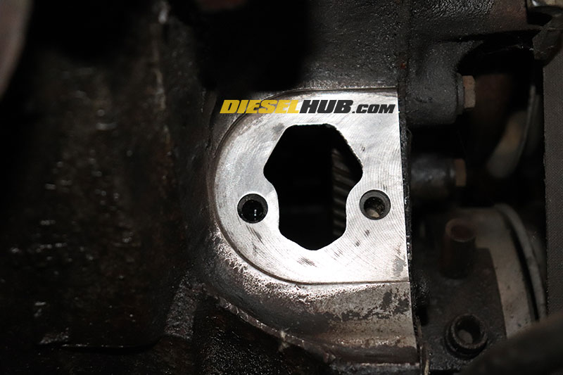
Fuel Pump Armature & Cam Lobe Position
When installing a new fuel pump on the 6.9L and 7.3L IDI, it is imperative to position the camshaft so that the fuel pump lobe is at its relief position and not its driving position (tallest part of the cam lobe is pointing upwards towards the top of the engine). Attempts to install the fuel pump while the tallest part of the cam lobe is pointing downwards (towards the sump) may easily result in damage to the pump. It is also possible for the armature to bind itself on the camshaft next to the fuel pump lobe. You will also find that the fuel pump will bind and must fight the spring pressure on the armature when the lobe is incorrectly positioned.
Figure 5 below identifies the proper and improper fuel pump lobe positions for installing a fuel pump. Also note that the armature must be installed beneath the cam lobe and not above it. Incorrect positioning of the fuel pump during installation will result in damage. Look through the fuel pump opening in the engine block with a flashlight to verify camshaft position. The engine can be rotated at the flywheel/flexplate to properly align the camshaft for fuel pump installation; these procedures are detailed below.

The 6.9L and 7.3L IDI diesel employed Carter fuel pumps from the factory. The armature design has since changed and no long resembles that of the original. The armature is roughly the same length, however the curvature and angle of the armature is significantly different; don't be alarmed that your replacement pump appears different than the original.

Parts List
| Part Description | Part Number(s) | Remarks |
| Fuel pump | Carter M60278 | [1] |
| Fuel pump gasket | Fel-Pro 6579 | [2] |
| Fuel pump inlet to hard line hose | --- | [3] |
| Fuel pump outlet line seal (sleeve at filter housing) | Dieselply DP-1611K | [4] |
| Fuel pressure test port | Dieselply DP-160401 | [5] |
| Fuel filter w/ factory water-separator bowl | Motorcraft FD3375 Wix 33217 Baldwin BF1222O Donaldson P553375 |
[6] |
| Fuel filter w/out water-separator bowl | Wix 33417 Baldwin FF1039 Donaldson P559853 |
|
| Engine oil filter | Motorcraft FL-784 | [7] |
[1] - May include fuel pump gasket
[2] - Good alternative to thin paper gaskets
[3] - 3/8 inch fuel hose
[4] - Parker sleeve; part number for Viton upgrade shown
[5] - Updated 1/4 inch flare fuel pressure test port/adapter
[6] - Replace fuel filter after replacing fuel pump
[7] - Replace engine oil after replacing fuel pump
How to Replace the Fuel Lift Pump on a 7.3 IDI Diesel
Click any thumbnail to view fullsize, detailed image

- Disconnect both negative battery cables.
- With the truck in park (in gear for manual transmissions) and the parking brake set, raise the vehicle, remove the front passenger side tire, and support the front of the vehicle on appropriately rated jack stands.
- Remove the inner fender (fender liner) on the passenger side.

- The inner fender has several components attached to the top of it that will require removal. The inner fender is secured with a variety of screws, bolts and clips. At minimal, a 1/4, 5/16, and 3/8 inch socket will be required to remove the hardware.
- With the inner fender removed, the fuel pump is visible behind the vacuum pump.

- Loosen the alternator mounting bolts with a 9/16 socket or wrench, then position the alternator clockwise towards the driver side to loosen the drive belts.

- Remove the alternator and vacuum pump drive pumps. The alternator does not need to be removed to access the vacuum pump, but it does provide a more spacious work area.

- Remove the (2) vacuum pump mounting bolts with a 10 mm socket, then secure it atop the engine and out of the way (using zip ties will ensure it does not slip and fall while working on the fuel pump). The vacuum pump hose does not need to be removed and provides ample freedom to arrange the pump out of the work area.

- Remove the hose clamp where the fuel pump inlet hose attaches to the hard line resting atop the frame rail.
- Separate the inlet hose from the hard line, then plug the hard line to prevent contamination. Be prepared for some fuel to leak from the hose when it is disconnected.

- Disconnect the fuel pump outlet line by unthreading the fitting with a 5/8 inch flare nut wrench.

- Disconnect the fuel pump outlet line at the fuel filter housing using a 3/4 inch flare nut wrench.
- Trace the line and remove the retaining clamp securing it to the engine block, then remove it from the engine bay and set it aside for cleaning.

- Remove the (2) fuel pump mounting bolts with a 9/16 inch socket. Note that a swivel socket may provide easier access.

- With the mounting bolts removed, pull the fuel pump away from the engine block. If it appears that there is restriction on the pump, it is because the armature is being depressed by the camshaft lobe; tilt the bottom of the pump upwards and towards the passenger side to help relieve this pressure.
- Thoroughly clean the fuel pump mounting pad so that it is free of debris, gasket remnants, and oil/fuel. To ensure the new gasket seals properly, this area must be relatively clean.
- Using a flashlight, inspect the position of the fuel pump cam lobe. If the tallest part of the lobe points upwards, the engine does not need to be rotated. If the lobe is not oriented in this manner, the engine needs to be rotated (refer to figure 5 above).
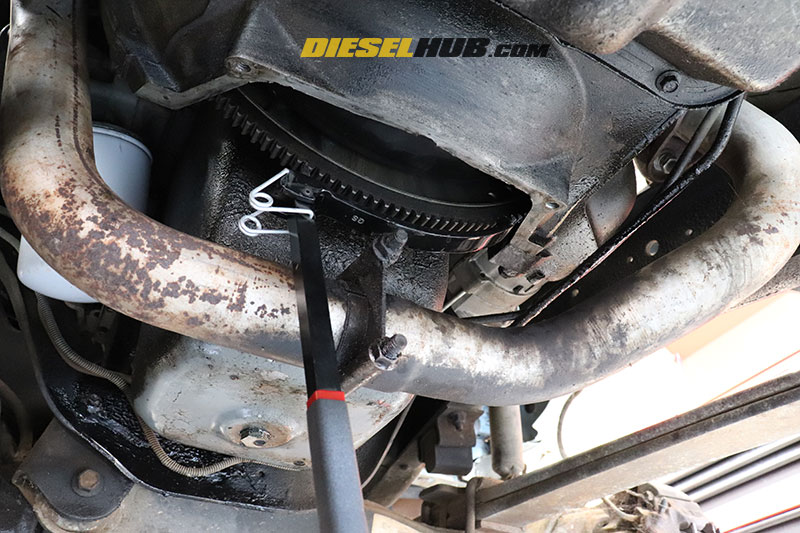
- If the engine needs to be rotated, remove the transmission inspection cover (4 to 5 bolts requiring a 3/8 inch socket).
- With the transmission in neutral (manual transmission only) and the parking brake set, use a flywheel/flexplate rotating tool to rotate the engine. Check the position of the camshaft lobe approximately every 20 to 30 degrees of rotation. When the lobe position matches that illustrated in figure 5, proceed with the installation of the new fuel pump.

- Prepare the new fuel pump by first installing the soft hose onto the fuel pump inlet.

- Partially install the fuel pump mounting bolts, followed by the fuel pump gasket. The mounting bolts should be used to help keep the gasket in place. A small dab of grease between the gasket and fuel pump mount can also be used to help keep the gasket in place, but use sparingly.

- Thoroughly clean the fuel pump outlet line (fuel pump to filter housing) and verify the condition of the gasket (sleeve) at the fuel filter housing side. If necessary, replace the gasket.

- Thoroughly clean the threads on the lower portion of the fuel pump outlet line. This is a flare fitting and requires no gasket, seal, or thread sealant.

- Install the new fuel pump, ensuring that the armature is installed beneath the fuel pump cam lobe. Tighten the mounting bolts in an alternating pattern to ensure proper installation. If the pump appears to want to position itself cockeyed while tightening the bolts, either the cam lobe is in the wrong position or it has slipped off the correct lobe.

- Reinstall the fuel pump inlet and outlet lines.
- Reinstall the vacuum pump and tighten the accessory drive bolts by setting the alternator tension.
- Install a new fuel filter and change the engine oil.
- Prime the fuel system per one of the aforementioned methods. We recommend you install the inner fender after confirming that there are no leaks at the fuel pump.


Editor, Diesel Hub