Applicable Models:
1994.5 - 1997 Ford F-250, F-350, F-Super Duty
1999 - 2003 Ford F-250, F-350, F-450, F-550 Super Duty
2000 - 2003 Ford Excursion
1995 - 1999 Ford Econoline E-350, E-Super Duty
2000 - 2003 Econoline E-350, E-450, E-550
2000 - 2003 Ford F-650, F-750
Applicable Engine(s):
7.3L Power Stroke V-8 diesel (7.3 DIT, T444E)
7.3 Power Stroke Oil Cooler Information
On a 7.3L Power Stroke engine, the oil cooler is positioned parallel to and just below the exhaust manifold on the driver side of the engine. It is attached to the front and rear of the engine block through adapters typically referred to as headers. The engine oil filter mounts against the rear oil cooler header, which also contains the filter bypass valve, oil pressure regulator, and engine coolant heater (block heater).
Internally, the engine oil cooler is a simple heat exchanger with separate passages for coolant and engine oil to flow through. Its purpose is to remove heat from the engine oil supply, transferring it to the cooling system where it can be expelled through the radiator. While oil coolers are widely common on diesel engines of all sizes, this device is of particular importance for the 7.3L Power Stroke because the HEUI injection system's high working pressures have the potential to generate substantial heat.

Engine coolant and oil are kept separate as they flow through the oil cooler by four large o-rings; two per header. In each header, one o-ring seals engine oil from leaking externally and the other seals the engine oil from the engine coolant (and visa versa). Like any o-ring, they are susceptible to becoming brittle and even cracking due to oxidation, heat, and chemical exposure.
Symptoms of an Oil Cooler Failure
Oil cooler failures are overwhelmingly the result of one or more failed o-rings; the heat exchanger itself is rather robust and cracked oil coolers are generally rare. On a 7.3L Power Stroke engine, an oil cooler failure will result in one of or a combination of the following:
- External oil leak originating between the oil cooler and one of the oil cooler headers
- Engine oil contaminating the engine coolant (oil in the coolant, collecting in the degas tank)
- Engine coolant contaminating the engine oil (coolant/water mixing with engine oil)
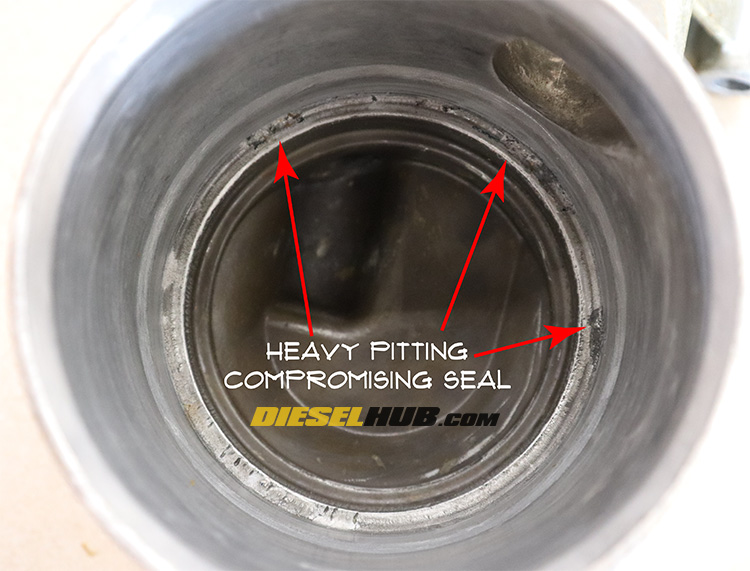
If not addressed promptly, an oil cooler leak can have catastrophic results depending on the type of failure and the degree of contamination between the lubrication and cooling systems. Despite o-rings seals typically being the primary failure point, oil coolers and even the headers are often replaced because they are susceptible to pitting in the o-ring sealing regions, preventing a proper seal during reassembly.
Oil in the Engine Coolant
When engine oil contaminates the cooling system it is generally found in the degas tank. A milky sludge, oily buildup, and/or cloudy black substance sticking to the side of the degas tank are all indicative of oil contamination. The exact appearance of the contaminated coolant is relative to the degree of contamination and how long the engine oil has been in the cooling system. Note that it is more common for oil to enter the cooling system than it is for coolant to enter the oil supply while the engine is running because the engine lubrication system operates at a higher pressure than the cooling system (oil pressure, even in the low pressure system, is higher than the water pressure in the cooling system).
Coolant (Water) in the Engine Oil
When engine coolant contaminates the lube oil system it generally turns the engine oil a milky color and/or causes the engine oil to thicken and, in extreme cases, turn into a thick sludge that is difficult to drain from the crankcase. Excessive coolant in the engine oil is a less common failure mode because the cooling system operates at a lower working pressure; fluids will display the natural propensity to flow from a region of higher to lower pressure and not the other way around. That said, it is still possible to have coolant in your engine oil and engine oil in your coolant. This is the result of engine oil being pushed into the cooling system while an engine is running and coolant slowly draining into the lube oil supply while the engine is off. Frequently checking your engine oil and coolant conditions is a simple way to catch oil cooler leaks at an early stage before excessive contamination can take place.
Causes of Repeated Oil Cooler Leaking & O-ring Failures
So you've replaced the oil cooler o-rings and it immediately began leaking; how did the o-rings fail so quickly? They likely didn't fail at all. The ends of the oil cooler heat exchanger and oil cooler headers are susceptible to pitting similar to that you might find inside of an old water pump housing. In many instances, corrosion and buildup can be removed from the oil cooler headers and they can be reused. In other instances, removing the buildup reveals a small cavity in the vicinity of an o-ring sealing surface that can allow fluids to escape around the seal. This is more common than one might think, and thus inspecting the oil cooler headers for pitting is extremely important.
Another noteworthy observation is that many brands of aftermarket o-rings do not fit or seat with the accuracy and precision that the Ford/International replacement o-rings do. This is simply one of those instances where there is not a suitable aftermarket replacement available that we could comfortably recommend; stick with the OEM o-rings and header gaskets to ensure a positive, long-lasting seal.
Moreover, it is also possible that one or both of the oil cooler headers developed cracks during removal, installation, or while seating them to the oil cooler. The headers are cast from soft aluminum and thus great care should be taken while handling them and seating the new oil cooler o-rings. If they are being tapped into place, only a rubber mallet or plastic faced dead blow hammer should be used and, ideally, a wooden block should be used to spread the impact across a larger surface area of the header. Ensure to use a liberal amount of clean motor oil or o-ring lubricant on the new o-rings and be patient during reassembly - these can be rather stubborn.
Oil Cooler Cleaning & Preparation
As previously mentioned, cleaning and inspection of the oil cooler and oil cooler header sealing surfaces is extremely important. If excessive pitting is present, the likelihood of obtaining a positive seal is low and the headers/oil cooler assemblies should be replaced as needed. We prefer to clean oil coolers with non-marring conditioning type brushes or discs because they will polish the sealing surfaces instead of scratch them. Even small scratches produced from stiff wire brushes or grinding burs can protrude deep enough to create a pathway for pressurized fluids.
The 3M Roloc product line (figure 3 below) is an excellent choice in conditioning products. In fact, many of Ford's service procedures assign the Scotch-Brite bristle discs (white, green, yellow products in figure 3 below) for cleaning critical contact areas such as cylinder head and engine block mating surfaces. The products are highly versatile and once you have the arbor, there is a myriad of options available for any clean-up task imaginable. When used in short sweeps at medium to high RPM, these products will remove dirt, grime, gasket material, and debris without compromising or marring the base material.

| Tool Description | Part Number |
| Roloc arbor, 1/4 inch shank | 07500 |
| Roloc bristle disc, 50 grit (green) | 18730 |
| Roloc bristle disc, 90 grit (yellow) | 07525 |
| Roloc bristle disc, 120 grit (white) | 07528 |
| Roloc conditioning disc, fine | 07515 |
| Roloc conditioning disc, medium | 07481 |
| Roloc conditioning disc, coarse | 07480 |
If you have access to an ultrasonic parts cleaner, they are an excellent first step in degreasing and de-griming the oil cooler headers. As for the oil cooler itself, tip it on one side and let it drain overnight; do not attempt to clean the oil passages with water or degreasing agents as it is extremely difficult to completely remove anything that enters the maze of narrow passages and contamination is likely. The sealing areas of the oil cooler and oil cooler headers need to be clean and free of corrosion/buildup before the new o-rings are installed and the pieces are reassembled.
Accessing the Oil Cooler
Accessing the front engine oil cooler header bolts and creating room to maneuver the oil cooler out of the engine compartment require that the power steering pump and its supporting bracket are removed. The process is slightly different for early and late style engines, particularly because the AC compressor is mounted on top of this bracket on OBS applications and the primary alternator is located here on the later Super Duty engines. Removal and reinstallation of the oil cooler itself is otherwise the same procedure across platforms, even for van applications.
These components can be removed individually, or the entire power steering pump bracket can be removed with the components attached and positioned out of the workspace. Both methods are outlined in the procedures section below. Removing the entire bracket and positioning it out of the way is preferred in that it is a moderately quicker process and does not necessitate the removal of any power steering hoses. The drawback is that reinstallation can be difficult for one person and a helper may be required to position the bulky, heavy bracket back in place. Both methods are correct and the path chosen is entirely dependent on the skill and confidence level of the individual.
Pressure Regulator & Bypass Valve Removal
Because the rear oil cooler header is home to the lube oil filter, it features two important components - the oil pressure regulator and the oil filter bypass valve. The oil pressure regulator is a simple spring type valve that provides a route to bleed off oil in the event that oil pressure exceeds a determined threshold. The filter bypass valve maintains oil flow through the critical engine lubricant circuits in the event that the oil filter should become clogged. In such an event, oil would enter the filter head and immediately cycle through the bypass valve. While this would result in unfiltered oil being circulated through the engine, it would prevent the engine from running dry and very rapidly wearing itself to expiry.
Neither component needs to be removed when repairing an oil cooler. In fact, on early style coolers these components are staked in place, meaning that they were installed and a punch was used to pinch the casting over the lip of these components, keeping them in place. These early style regulators and valves should not be touched unless absolutely necessary as they have a tendency to work themselves loose, thus the reason why the later types use a snap ring to secure the components in place.

Removal and reinstallation of these two components is covered in the procedures below. You may consider complete disassembly, cleaning, and inspection of these two components if 1) you have had a severe oil-coolant contamination issue in which the engine oil has turned into a thick greasy paste and 2) your oil cooler header is a later style that uses a snap ring to secure these components, permitting removal and reinstallation without concern of a future failure. Regardless of the situation, we recommend against disassembling the staked on type bypass valve and pressure regulator.
Oil Cooler Replacement Part List
| Part Description | Part Number(s) | Remarks |
| Oil cooler o-ring, inner (green) | Ford 1C3Z-6C610-BA | [1] |
| Oil cooler -ring, outer (black) | Ford 1C3Z-6K649-BA | [1] |
| Front oil cooler header gasket | Ford F7TZ-6A636-AAA | [2] |
| Rear oil cooler header gasket | Ford F4TZ-6A636-A | [2] |
| Engine oil cooler assembly | Ford 1C3Z-6A642-AA | --- |
| Front oil cooler header | Ford F4TZ-6881-B | --- |
| Rear oil cooler header, F-Series | Ford F81Z-6881-BA | --- |
| Rear oil cooler header, E-Series | F4TZ-6881-C | --- |
| Oil cooler bolt kit | Ford W300088 | Reusable, replace as needed |
| Cooling system flush compound | Motorcraft VC-1 | [3] |
| Engine coolant concentrate (OEM) | Motorcraft VC-5 green | [4] |
| Engine oil filter | Motorcraft FL-1995-A | [5] |
[1] - Ford sells in packages of (4); only (2) are required per oil cooler. Some parts distributors sell individually or in pairs for convenience.
[2] - Oil cooler header to engine block gasket
[3] - If engine oil has contaminated the cooling system, flush one to two times or until all oil is removed
[4] - OEM green concentrated engine coolant for 7.3L Power Stroke engines
[5] - Change engine oil and filter after oil cooler is reinstalled
Oil Cooler Headers for E-Series Vans
The front oil cooler headers are the same for E-Series van and F-Series truck applications, however the rear oil cooler header is different. Specifically, the rear oil cooler header has a different pitch for the engine oil filter that permits service in the tighter van chassis. Unfortunately the rear oil cooler for van engines, Ford part number F4TZ-6881-C, has been discontinued and is now considered obsolete. At time of publishing, there were no suitable aftermarket replacements available, and the supply of NOS units was dwindling. Junkyards, second hand marketplaces, and obsolete part dealers remain the best places to secure replacement rear oil cooler headers for van applications.
Methods for Seating the Oil Cooler Headers
Generally speaking, it takes quite a bit of persuasion to properly seat the headers onto each side of the oil cooler. The clearances are tight, the o-rings are not particularly soft, and the header castings are brittle aluminum; while a lot of force is needed, preventing a header from cracking is a delicate operation. Likely the most common method of seating the headers after replacing the o-rings is with a dead blow hammer. To prevent cracking a header, lay a block of wood (2x4 or 2x6 lumber) over the header and hit the wood, not the header directly. To prevent the opposite end from encountering damage, lay it on a block of wood as well and wrap the exposed heat exchanger end in a large shop rag to keep debris from getting inside as the block deforms.
7.3 Power Stroke Oil Cooler Removal Procedures
Click any thumbnail to view fullsize, detailed image

- Disconnect both negative battery cables.
- Place a suitable container beneath the engine oil pan and remove the drain plug, allowing the oil to drain.
- Locate the drain valve on the lower driver side corner of the radiator. If desired, secure a 3/8 inch hose at the nipple to reduce coolant splashing while the radiator is draining. Place a container beneath the drain valve.
- Open the radiator drain valve by rotating it counterclockwise until coolant begins to drain; allow to drain completely before the oil cooler assembly is removed.

- While the radiator is draining, remove the the airbox lid, followed by the intake air tube feeding into the turbocharger compressor inlet. Note that it may be convenient to remove the entire airbox/battery box assembly.
- Remove the driver side intercooler tube (late engines only).
- Remove the engine serpentine belt.

- It is necessary to remove the alternator/power steering bracket in order to access to front oil cooler header. This procedure is different for early and late model engines, but in either case their are two options: remove the bracket with the alternator and power steering pump still attached (left), or remove the individual parts first. While we have outlined how to remove the individual parts below, take note that it is less steps to remove the bracket with the accessories still attached. The downfall of this method is that it is difficult to reinstall the heavy bracket without a helper.

- For late engines, remove the alternator. On early engines, remove the AC compressor and position/secure it out of the workspace without bending or kinking the refrigerant lines.
- Remove the power steering pump pulley, followed by all (3) power steering hoses.
- Remove the power steering pump, which is secured to the bracket with (3) bolts requiring a 17 mm socket.

- Remove the power steering pump bracket with a 13 mm socket; a total of (4) bolts secure it to the front cover.

- Locate the passenger side coolant passage plug threaded into the engine block near the rear oil cooler header. Note that there are (2) pipe plugs in this location; the upper plug is the coolant drain, the lower plug is an oil return port.
- Place a drain pan beneath the rear oil cooler header, remove the coolant plug with a 5/16 inch square drive socket, and allow coolant to drain from the engine block passage.

- Remove the engine oil filter from the rear oil cooler header.
- Disconnect the engine block heater connector from the heating element. A metal clasp secures the connector in place; manipulate and unsecure the clasp, then pull the connector straight out of the heating element (the connector itself does not rotate, it pulls straight out).

- Remove the (2) front oil cooler header mounting bolts with a 10 mm socket.

- Remove the (3) rear oil cooler header mounting bolts with a 10 mm socket while supporting the oil cooler so that it does not fall.
- Apply gentle, alternating up-and-down pressure on the front and rear oil cooler headers to break the gasket seal; it is going to leak a small amount of engine oil and coolant that has remained suspended in the heat exchanger and headers.

- Maneuver the oil cooler out from the rear of the engine compartment. It will need to be twisted, tilted, and repeatedly reoriented as it's a tight fit.
- Place the oil cooler upright in a container or on a workbench to drain completely. The heat exchanger passages on the oil side form a particularly dense labyrinth that slows the oil from draining.
- Liberally apply penetrating fluid to the front and rear headers where the o-rings seat. If removing the block heater element, apply penetrating fluid to the threads.

- Remove the engine block heater with a 1-1/8 inch socket. Note that these can be particularly stubborn and an impact gun may be necessary to break it loose.

- Set the jaws of a vice such that the oil cooler header will not pass through, but the heat exchanger will, then position the front or rear oil cooler atop the vice. Do not clamp the heat exchanger tube in the vice as it will likely become damaged.
- Tap the opposing header with a dead blow hammer to separate the oil cooler tube from one of the headers. Flip the assembly around and repeat for the other side so that both headers are removed. These can be extremely stubborn since the o-rings have likely become hard and brittle.

- Remove the old o-rings from both sides of the oil cooler heat exchanger. If the o-rings are stuck, simply cut them off.
- If the oil cooler itself is being reused, thoroughly clean the o-ring mounting surfaces on the oil cooler heat exchanger, ensuring they are perfectly clean and free of any previous remnants. Do not allow any debris or contaminants to enter the oil passages as they will be extremely difficult, if not impossible to remove. Inspect the coolant passages and clean as required with narrow brushes from a firearm cleaning kit or weed eater line.

- Note that the next several steps refer to disassembly of the oil filter bypass valve and pressure regulator. Do not attempt to remove the bypass valve and/or pressure regulator if it is a staked-on type that is secured without a snap ring. Even for those secured with a snap ring, these steps are optional.
- Remove the oil filter bypass valve snap ring.

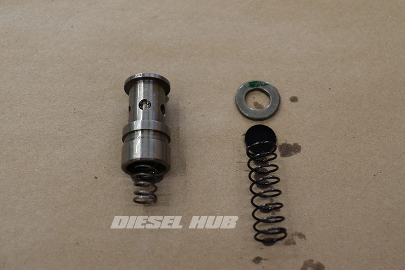
- Carefully remove the bypass valve components from the rear oil cooler header.
- Note that the image at left illustrates the proper orientation of these pieces for reference and reassembly.

- Remove the pressure regulator snap ring.

- Remove the oil pressure regulator components.
- Note that the image at left illustrates the proper orientation of these components for reference and reassembly.

- Remove the pressure port plug from the rear oil cooler header with a 7/16 inch socket.

- If the oil cooler headers are being reused, thoroughly clean them. All gasket making surfaces should be clean and free of debris.

- The internal o-ring mounting locations are of the utmost important when cleaning the oil cooler headers. Any residual debris will easily compromise an o-ring seal. As previously discussed, the headers should be thoroughly inspected for pitting prior to reinstallation. Excessive pitting is indicative of a poor cooling system service regiment and dictates replacement of the header(s).

- Do not negate to clean the exterior of the oil cooler headers to ensure that grease and grime does not contaminate the reinstallation process. If the headers are good and clean, leak detection may be made easier also.
7.3 Power Stroke Oil Cooler Reassembly & Installation Procedures
- If the oil filter bypass valve and/or pressure regulator were removed, the components should be thoroughly cleaned and lubricated with clean motor oil prior to reassembly.
- Some of the following steps may not apply depending on which items are being replaced and which are being reused.

- Reinstall the pressure regulator and secure it in place with the snap ring.

- Reinstall the oil filter bypass valve and secure it in place with the snap ring.

- Reinstall the pressure port with thread sealant (recommend Loctite 545); do not overtighten, the aluminum header is quite susceptible to cracking and the plug is a tapered thread.

- Liberally coat the replacement oil cooler o-rings with clean motor oil.
- Apply clean motor oil to the o-ring mounting lands.
- Install the large inner o-rings (green) followed by the smaller outer o-rings (black).

- Generously lubricate the o-ring mating surfaces of the oil cooler headers with clean motor oil or assembly lube.

- Install the rear oil cooler header, noting that the protruding dowel on the heat exchanger must line up inside the relatively wide slot on the header (pictured).

- Install the front oil cooler header, noting there is no indentation or slot for the dowel on the heat exchanger.

- Verify proper fitment and seating of the o-rings in both the front and rear oil cooler headers; you should not be able to see either o-ring once the headers have been seated properly. Note that if the oil cooler is not seated to the proper depth inside of the oil cooler headers, it will be blatantly obvious when installation is attempted as it will appear too long to mount against the engine block pads.

- Rotate the oil cooler headers so that the mounting surfaces (that mounts to the engine block) are roughly parallel to each other.

- Thoroughly clean the oil cooler header mounting pads on the engine block/front cover, removing any and all remnants of the old gasket material. Run a finger around the openings and ensure there is no buildup or burrs that are going to catch a gasket as it is being seated.

- Lightly coat the rubber sealing areas of the oil cooler header gaskets with clean motor oil.

- Maneuver the oil cooler assembly into place. Although easier with two people, it's very possible to install one alone. You may need to alternate between the top and bottom access points to get the correct orientation and range of motion to position it in place.

- Line up the front oil cooler header, slide in the gasket, and then install one of the front oil cooler header bolts (leave loose). The engine mount cradle serves as a good rest for the oil cooler when repositioning.

- Line up the rear oil cooler header, slide in the gasket, and then install one of the rear oil cooler header bolts. The oil cooler will still rotate as necessary to get the orientation correct. If the bolt holes do not line up, one or both of the oil cooler headers is not seated properly; remove and re-seat.
- Install the remaining front and rear oil cooler header bolts hand tight.
- Torque all oil cooler header bolts to 18 ft-lbs in an alternating fashion; do not overtighten.

- If removed, reinstall the engine block heater element. Apply sealant to threads (recommend Loctite 545), do not overtighten.
- Install a new engine oil filter.
- Reinstall the power steering pump, alternator, AC compressor, and bracket as applicable.
- Reinstall the serpentine belt. Close the radiator drain valve, reinstall the block drain plug, and refill the cooling system.
- Reinstall the oil pan drain plug and fill the engine with new motor oil. Verify engine oil level, start engine, then check for leaks and fluid cross-contamination. If cross-contamination has previously occurred, a full cooling system flush is required at this time.

