Ford did not produce the F-250 or F-350 for the 1998 model year and instead leapt between 1997, the end of the OBS, to the 1999 Super Duty. However, they did produce the E-Series as a 1998 model with the 7.3 liter Power Stroke engine. Thus, 1998 was technically a transformative year for the 7.3 liter even though there were not 1998 model year pickup trucks. This matters because one of the major changes was the turbocharger, which added a wastegate amongst other noninterchangeable updates.
Furthermore, the 1999 model year was a confusing one because there was a mid-model year update to the 7.3 liter Power Stroke in which it received a turbocharger with a larger compressor outlet. The 1999 model year is therefore split between two turbocharger types most often categorized as either an "early" or "late" style. This was the last major update for the 7.3 liter engine and thus 2000 to 2003 engines are essentially identical to the late 1999 models. When acquiring replacement parts a 1999 model year engine, it is important to know whether it is an early or late style.

Simple enough, the compressor outlet on an early 1999 turbocharger has an inside diameter of 2 inches and the late 1999 turbocharger has a compressor outlet or approximately 2.65 inches. Turbocharger removal is much more intimidating than it is difficult because there are a number of steps and many systems with small parts that must be removed or repositioned to gain access to the turbo. Furthermore, the turbocharger is a fairly heavy component - the late 1999 and newer style turbo is 30 lbs of dead weight without the pedestal. This makes it somewhat awkward to maneuver it in and out the engine without crashing into another component.
| Component | Part Number(s) | Remarks | |
|---|---|---|---|
| Turbocharger install kit | Early 1999 | DP-1207K-E | [1] |
| Late 1999-2003 | DP1208K-L | ||
| Up-pipe collector clamp | Ford F81Z-8287-EA | [2] | |
| Downpipe clamp | Ford XC3Z-5A231-AA | [2] | |
| Compressor outlet clamp | Early 1999 | Ford F81Z-8287-DA (MotorcraftYF2488) |
[2] |
| Late 1999-2003 | Ford 1831214C1 | ||
[1] - Basic turbocharger install kit, includes new bolts to mount the turbo to the pedestal, new o-rings to mount the pedestal to the block and the turbo to the pedestal, and a new compressor outlet seal
[2] - Clamps are reusable if not damaged, recommend cleaning threads; replace if bent/damaged
Turbocharger Removal
Click any thumbnail to view fullsize, detailed image

- Disconnect both negative battery cables.
- Remove the corrugated intake tube between the air filter box and the CCV adapter (mouthpiece) mounted to the valve cover bracket.
- If the intercooler tubes are to be removed completely (not required to pull turbo), remove the entire battery tray/filter box for better access to the driver side of the intercooler.
- Loosen the hose clamps at the cold-side intercooler tube boot where it connects to the intake "spider" manifold.
- Disconnect the cold-side intercooler tube from the "spider" manifold.
- If removing the tube entirely, loosen the clamps at the intercooler and remove the cold-side intercooler tube from the engine compartment.
- Loosen the hose clamps at the hot-side intercooler tube boot where it connects to the intake "spider" manifold.
- If removing the tube entirely, loosen the clamps at the intercooler and remove the hot-side intercooler tube from the engine compartment.
- Loosen the hose clamp(s) at the rubber crankcase vent elbow.
- If the crankcase vent elbow is original, it may have a hose clamp on one end and a band at the other; loosen the hose clamp and ignore the band.

- Remove the (2) bolts that mount the crankcase vent adapter to the valve cover bracket with an 8 mm socket.
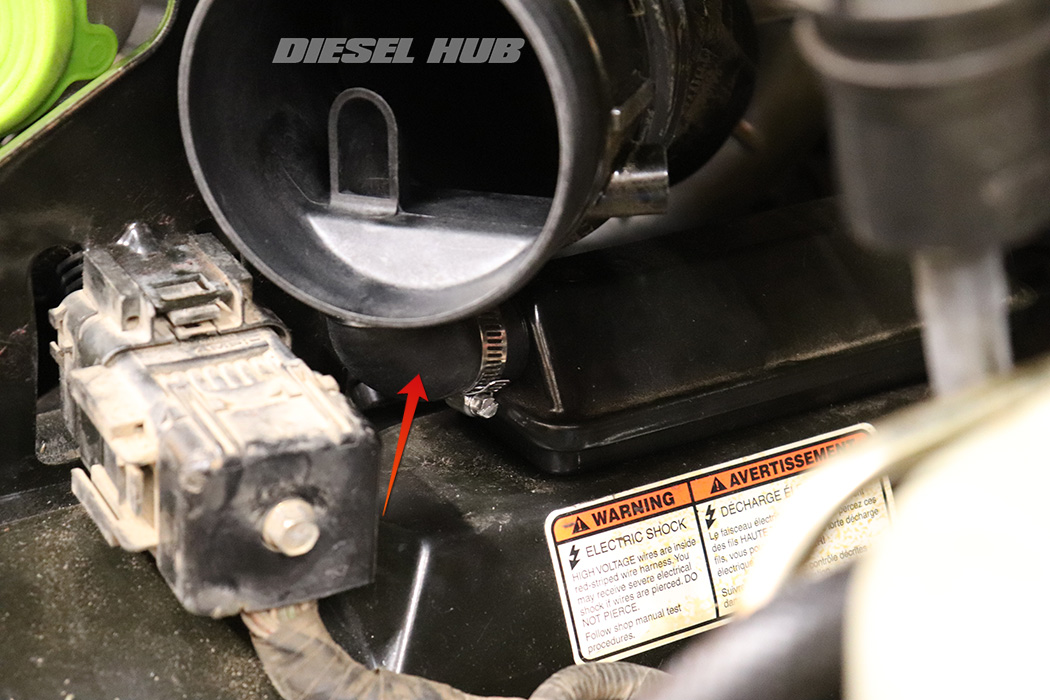
- Pull the small green hose out of the intake tube that connects the crankcase vent adapter to the turbocharger compressor inlet.
- Loosen the clamp connecting to the turbocharger compressor inlet.

- Twist the crankcase vent adapter and adjacent intake tube upwards to separate the CCV elbow, then twist and pull to disconnect the intake tube from the turbocharger.
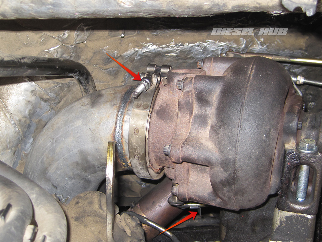
- Disconnect the small red hose from the wastegate actuator mounted to the turbocharger.

- Disconnect the red/green hose combination from the wastegate solenoid mounted to the upper face of the intake manifold.
- Disconnect the wastegate solenoid connector.
- Remove the intake air heater (IAH) stud nut, followed by the power wire, insulator, and ground wire.
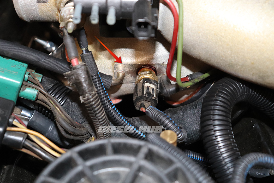
- Disconnect the vacuum hose fitting at the base of the intake manifold next to the intake air temperature (IAT) sensor.
- Completely remove the red/green wastegate solenoid lines from the engine compartment.
- Disconnect the IAT sensor connector.
- Disconnect the MAP sensor hose from the intake manifold.
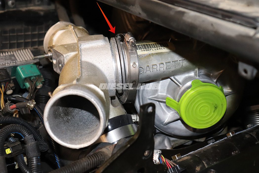
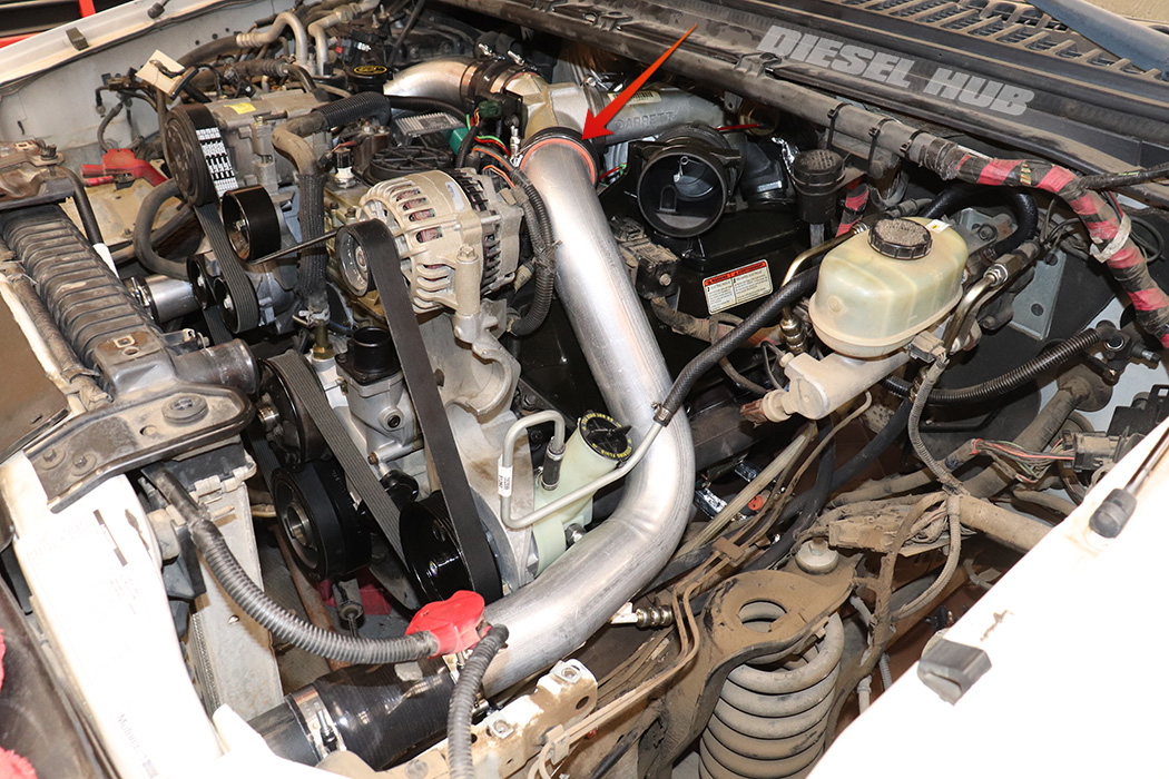
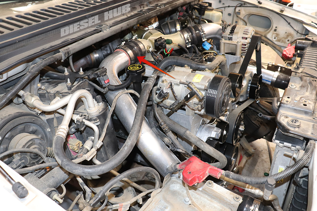
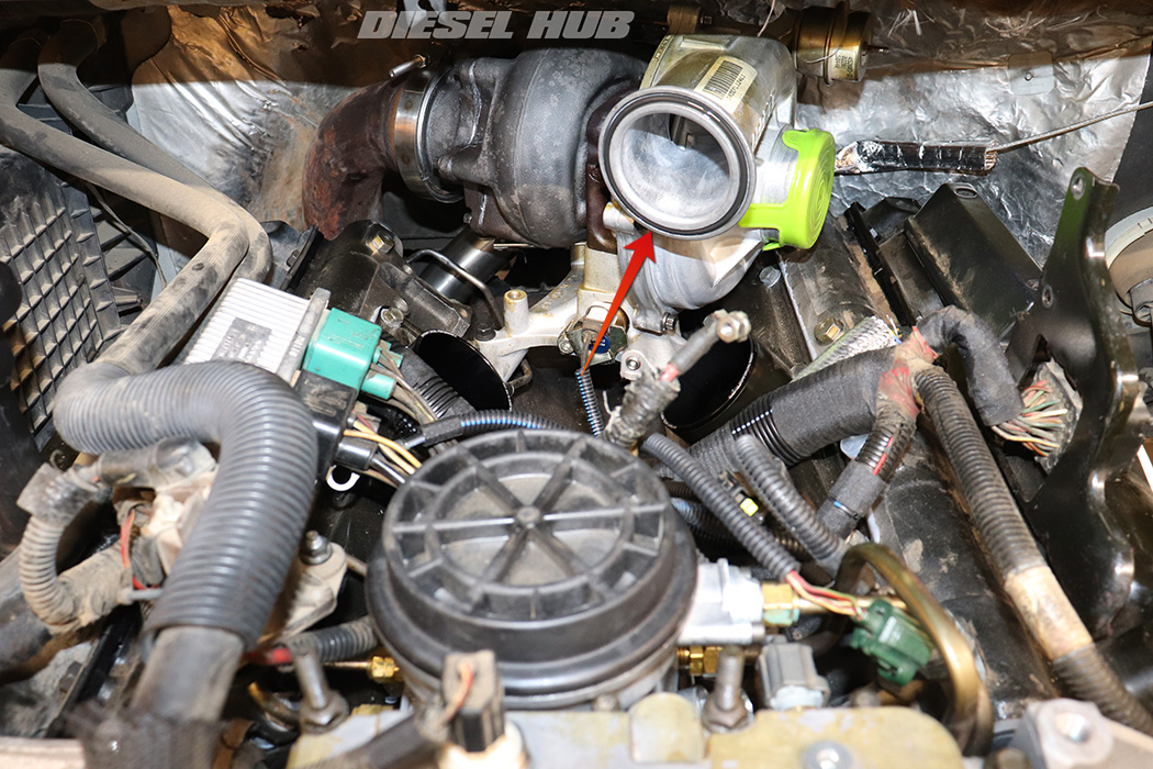
- Generously loosen the clamp that secures the intake manifold to the turbo compressor housing outlet.
- Maneuver the clamp over the flange and onto the compressor housing.
- Generously loosen the clamps for the boots that connect the "spider" manifold to the intake plenums at both cylinder heads.
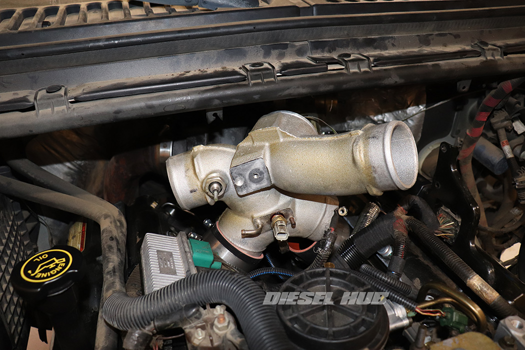
- Remove the intake manifold by working it side-to-side while pulling upwards.
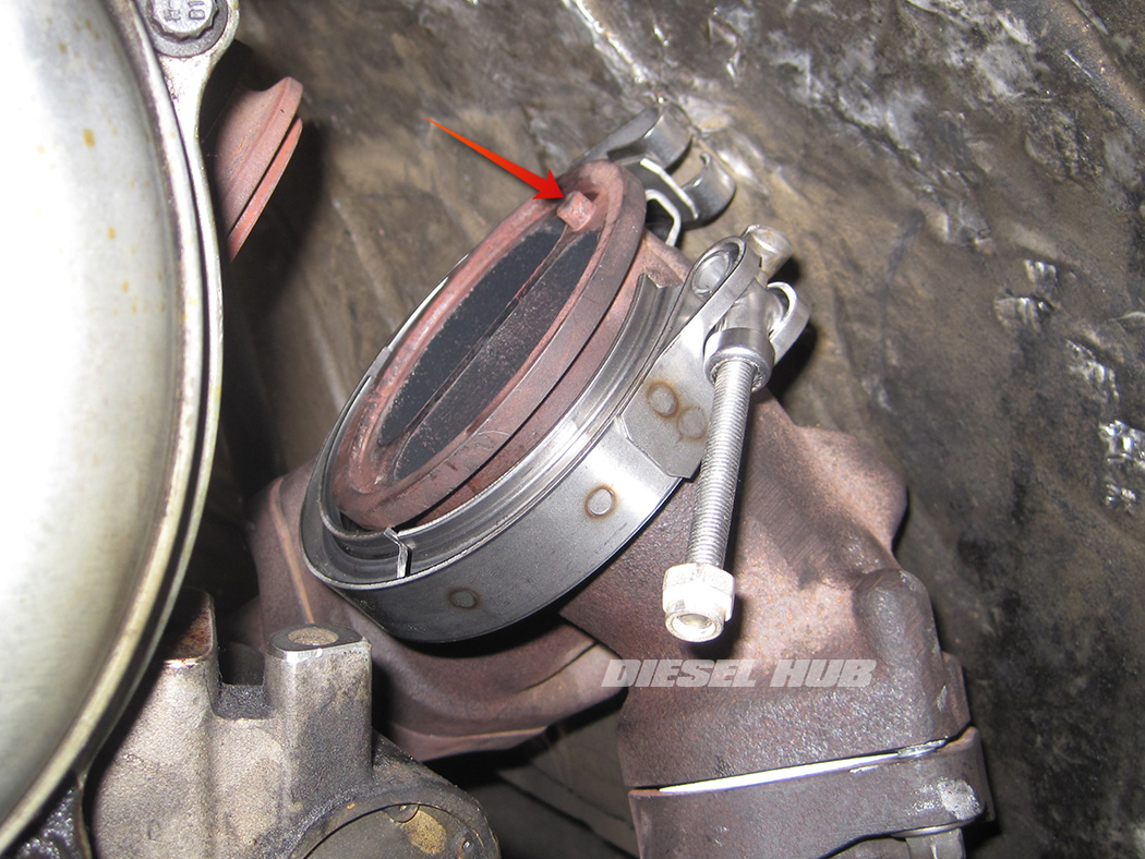
- Remove the intake manifold to compressor housing Marman clamp.
- Note that there is an o-ring seal between these two components that must be replaced before the turbocharger is reinstalled.
- Generously loosen the downpipe to turbine outlet Marman clamp with an 11 mm deep socket.
- Slide the clamp over the downpipe and off of the turbine housing.
- Separate the downpipe from the turbine housing and let it hang. Sometimes the downpipe fuses to the turbine housing due to corrosion. It may be necessary to tap the pipe or pull from below to separate the joint.
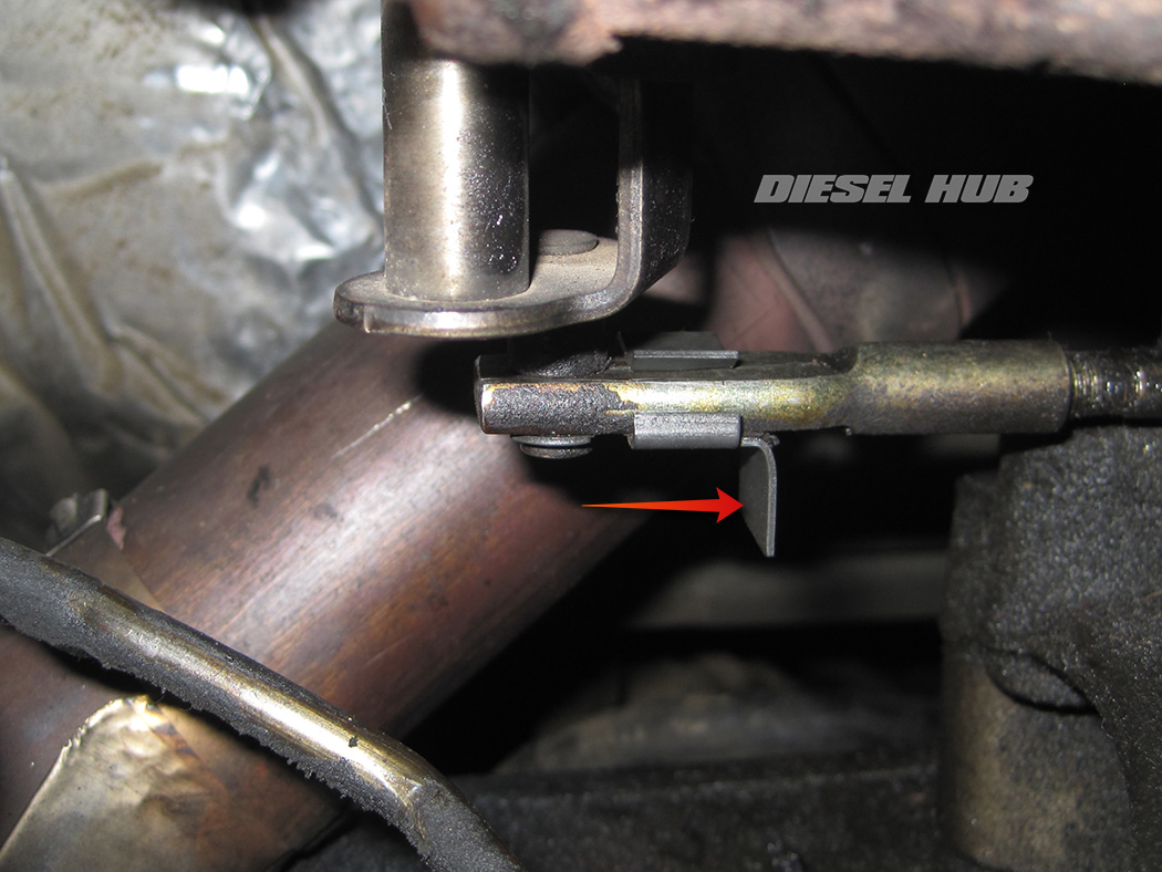
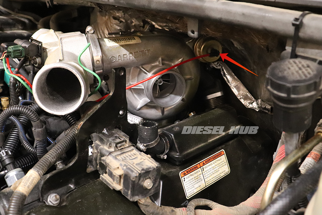
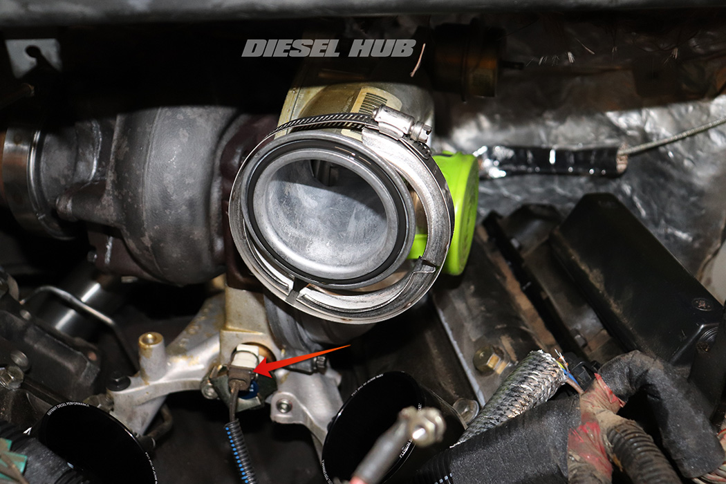
- Reach beneath the turbine housing and slide the latch on the exhaust backpressure valve actuator rod towards the driver side.
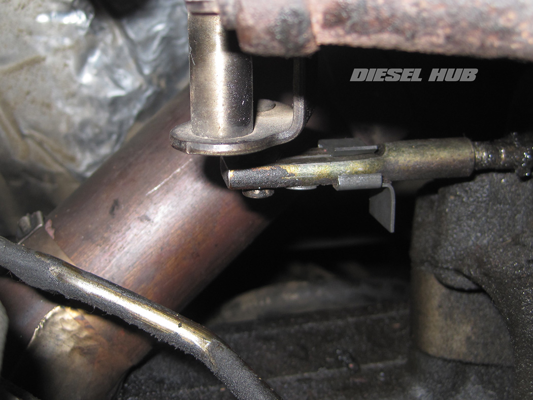
- Note - rod shown in unlatched position in image at left.
- The latch must be unlocked prior to removing the turbocharger from the pedestal or it will hang up on the actuator rod.
- Generously loosen the Marman clamp that secures the up-pipe collector to the turbine housing with an 11 mm deep socket.
- Maneuver the clamp off the turbine housing and onto the collector. Alternatively, the clamp can be completely removed. If the clamp is not positioned off of the turbine housing it will catch and prevent the turbo from being removed.
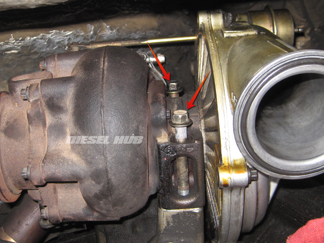
- Remove the (2) bolts that secure the turbocharger to the pedestal with a 15 mm socket and extensions. These mounting bolts pass through the turbo center-section between the compressor and turbine housings.
- Tilt the turbocharger forward and lift upwards to separate it from the pedestal.
- Carefully maneuver the turbocharger out of the engine compartment - it is heavy and awkward to handle. The potential to bang the turbo against an intake plenum is high, and it will easily dent this part.
- If applicable, disconnect the exhaust backpressure solenoid connector at the front of the pedestal.
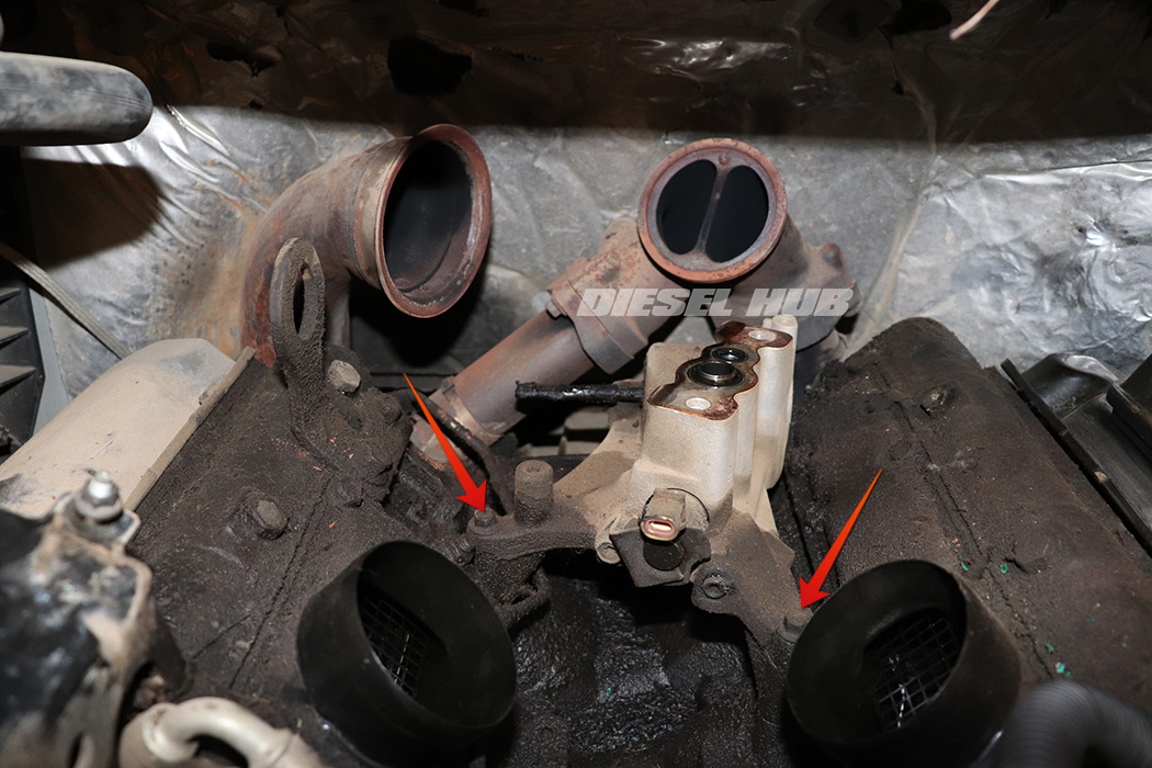
- Remove the (4) turbocharger pedestal bolts with a 10 mm socket and appropriate extensions. The pedestal mounts to the engine valley with (2) bolts near the front and (2) bolts near the rear.

- Maneuver the turbo pedestal upwards and then out of the engine compartment.
- Remove the turbocharger pedestal o-rings from the engine valley; these should never be reused.
- Cover the oil supply and drain line openings to prevent debris infiltration.
- Recommend cleaning the engine valley while it is exposed for improved leak detection later on.
Turbocharger Installation
- If the turbocharger has been disassembled, repaired, sitting off the vehicle for an extended period of time, or a new unit is being installed it should be pre-lubed prior to assembly.
- To pre-lube a turbocharger, carefully pour clean motor oil or assembly lubricant into the supply and drain openings in the bottom of the center section with the turbocharger positioned upside down.
- Rotate the turbine wheel by hand to disperse the motor oil inside the center section.
- Tip the turbocharger right-side-up and allow it to drain. Repeat another 1 to 2 times, allow turbocharger to drain before installing.
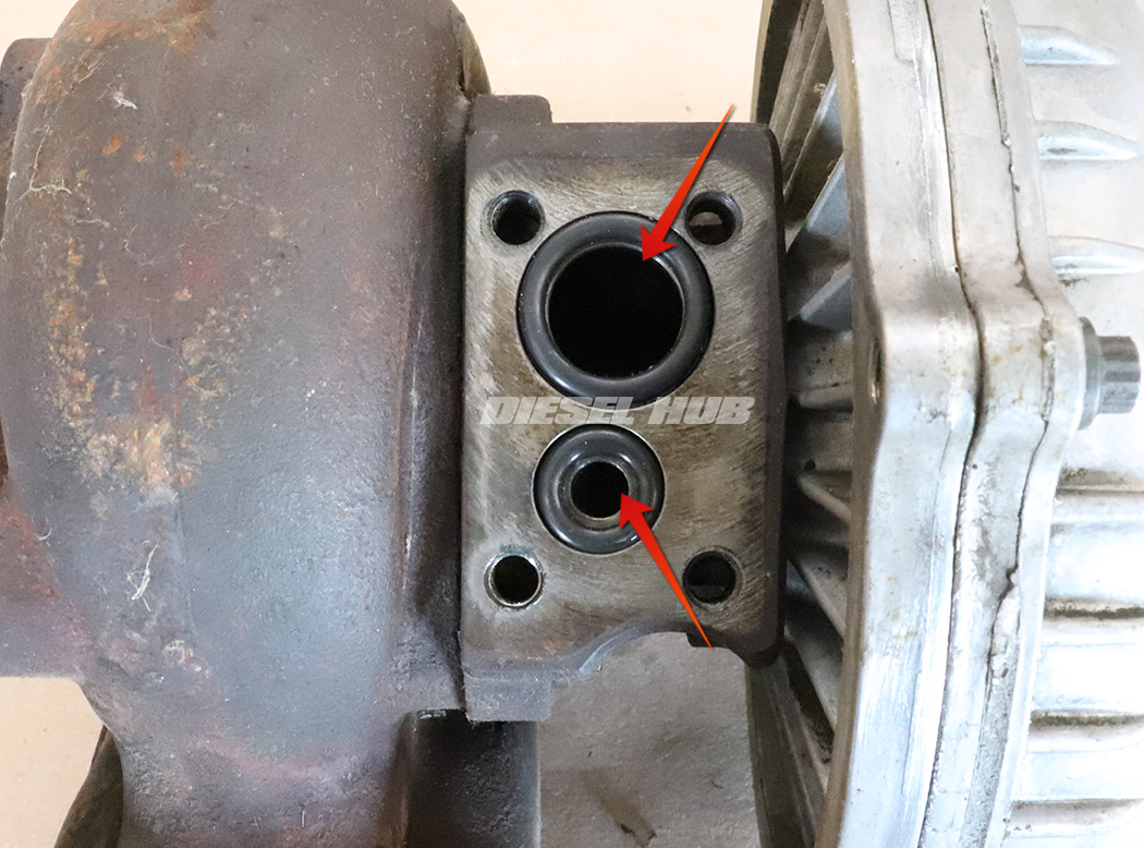
- Lubricate the engine block to pedestal o-rings with clean motor oil, then install them into the corresponding oil supply/drain pad openings.
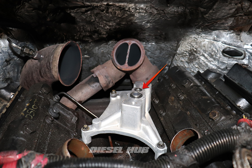
- Carefully set the pedestal into place and line up the bolt holes. Take a visual inspection to ensure an o-ring is not obviously pinched.
- Install the turbo pedestal bolts and torque to 18 ft-lbs in a front-to-back alternating fashion.
- Lubricate and install the pedestal to turbocharger o-ring seals onto the pedestal pad.
- Install the downpipe clamp so that it will not interfere with installation of the turbo.
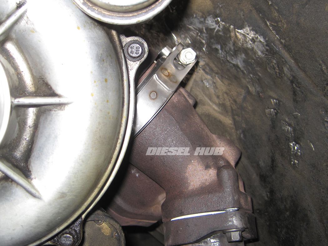
- Install the up-pipe collector clamp so that it will not interfere with installation of the turbo (shown).
- Carefully maneuver and set the turbocharger into place.
- For the turbocharger to mate to the up-pipe collector, the hole in the turbine inlet must be aligned with a pin at the top of the collector.
- When it has been confirmed that the collector/turbine housing are properly aligned, maneuver and install the clamp.
- Torque the clamp to 62 in-lbs.
- Install the turbocharger to pedestal mounting bolts and torque to 18 ft-lbs. If it is difficult to align these bolts the up-pipe collector to turbine housing clamp can be loosened slightly, but don't lose the alignment between the pin and hole.
- Maneuver and connect the downpipe to the turbine housing outlet. Torque the clamp to 50 in-lbs.
- Reinstall the EBPV actuator rod and lock the latch.
- Install a new o-ring at the turbocharger compressor outlet.
- The remainder of the components are reinstalled in reverse order.
- It is recommended that the engine oil and filter be changed shortly after completing this operation since the crankcase has potentially been exposed.

