A king pin is a very simple, reliable pivot system with the ability to withstand a significant amount of weight - thus they are the steering axle system of choice in the medium and heavy truck segments. King pin axles are obsolete in cars and light trucks as independent front suspension provide far better ride quality.
Worn king pin bushings typically result in erratic side-to-side movement of the tires, difficultly keeping the truck driving in a straight path (wandering), and excessive play in the steering system. Before assuming that the king pins are to blame for steering issues, inspect the condition of the ball joints at the steering knuckles and tie rod assemblies. King pins are always replaced in pairs, never on one side or another. Additionally, you will need to replace the inner and outer wheel bearings before reinstalling the wheel hub assemblies. The wheel bearings are somewhat expensive on the C3500HD do to its GVWR but they should not be reused.
C3500HD King Pin Service Parts List
Part Description |
Part Number(s) |
Remarks/Notes |
King pin service kit |
[1] |
|
Inner wheel seal |
[2] |
|
Inner wheel bearing |
[3] |
|
Outer wheel bearing |
[1] Services both king pins, driver and passenger side.
[2] Two piece wheel seal.
[3] Includes bearing race.
C3500HD King Pin Rebuild Procedures
Click any thumbnail to view fullsize, detailed image
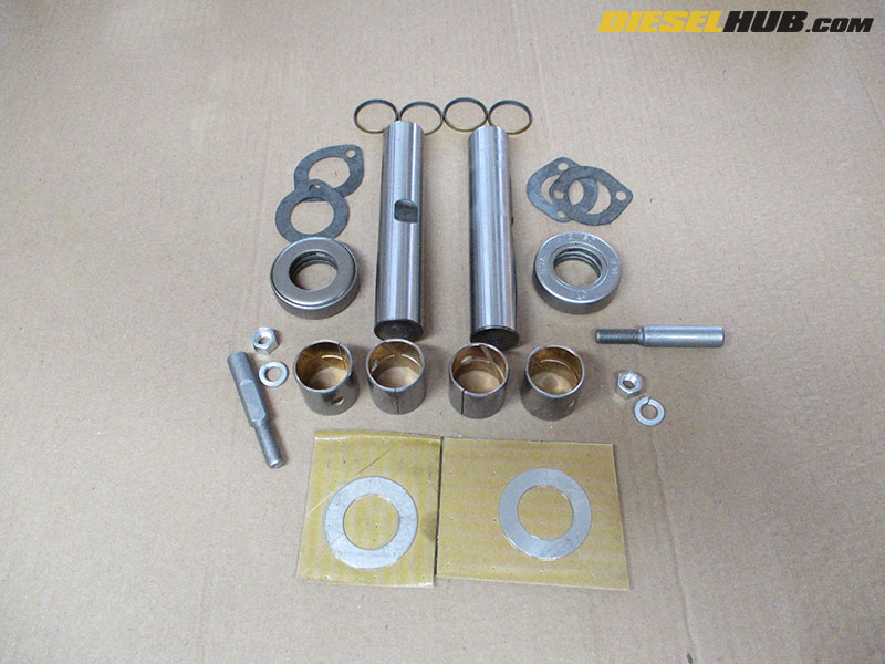
• The ACDelco king pin set is available with metal or composite bushings. Here, we're installing the metal bushing set. It requires the bushings to be reamed to the correct dimension to obtain proper fitment of the king pin itself.
The kit includes all hardware associated with rebuilding the king pin system - king pins, bushings, king pin retainer, gaskets, seals, lower bearings, and shims.
• Break the lug nuts loose, then jack up the front end and secure it with jack stands. Remove the tire.
• Disconnect the brake line from the bracket located at the top of the steering knuckle (it slides out after removing the spring clip) to obtain additional "slack" so the brake caliper can be hung when removed without pulling on the line.
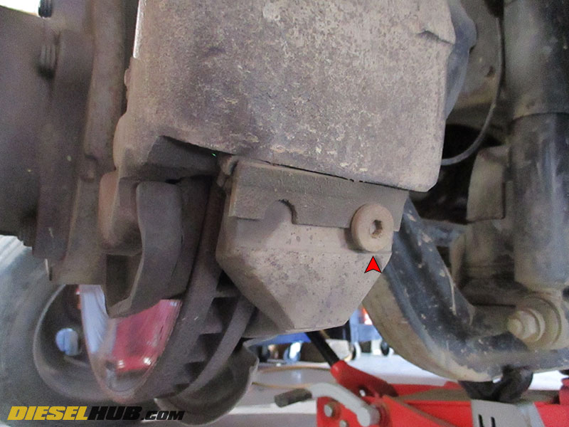
• Locate the brake caliper slide at the bottom of the caliper. Remove the bolt securing the slide (1/4" Allen).

• Use a punch (preferably brass) to pound out the caliper slide, freeing the brake caliper. Remove the caliper from the rotor and hang it using a piece of wire (do not hang by the brake line).

• Remove the dust cap from the wheel hub assembly.
• Remove the cotter pin from the castle nut.
• Remove the castle nut from the spindle (1-1/4" socket).
• Remove the entire wheel hub/brake rotor assembly from the spindle and set aside.
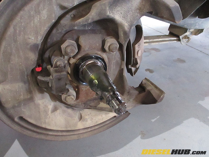
• Remove the rubber piece of the inner wheel bearing and discard.

• Remove the brake rotor backing plate (3 bolts, 1/2" socket).
• Remove the wheel speed sensor bracket at the top of the king pin knuckle (1/4" 12 point socket). Do not remove the sensor itself, just the bracket adjacent to the brake hose bracket.
• Remove the 4 bolts securing the brake caliper bracket to the king pin knuckle (1-1/8" socket).
• Set the brake caliper bracket aside and hang the wheel speed sensor safely out of the way.
• Remove the remaining bolt near the Zerk fitting at the top of the king pin knuckle (1/4" 12 point socket). Gently pry and remove the top plate from the king pin knuckle.
• There is another plate sealing the bottom of the king pin knuckle. It is a mirror image of the top plate. Remove the 2 bolts, then the plate (1/4" 12 point socket).
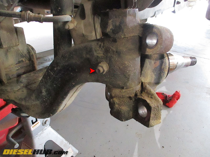
• Remove the king pin retaining bolt nut (9/16" socket).
• Drive the retaining bolt out of the axle using a brass hammer or punch. These pins can be stubborn and may mushroom if driven using a steel hammer, making removal more difficult.
• Drive the kin pin out of the knuckle and axle assemblies using a brass punch. The king pin can be stubborn. If seized, heat may be applied to the top and bottom of the knuckle. With the king pin out, remove the steering knuckle/spindle assembly.
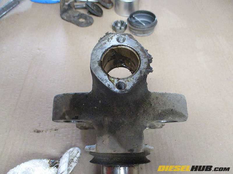
• Drive out the king pin bushings from the top and bottom of the knuckle. Find a socket that fits inside the knuckle but NOT the bushing. This can be used to drive out the bushing with a press or hammer. It is generally a tight fit, so it may take some effort.
• With the bushings removed, thoroughly clean the knuckle/spindle assembly or any dirt, dust, debris, and grease. We went the extra mile and sandblasted the entire assembly after covering the spindle as not to compromise the machined surface.

• Grease the inside of the knuckle and drive in the new king pin bushings. Once again, the fitment is very tight. We used a small wooden board to hammer them into place. Make sure the bushings are flush with the top of the knuckle (any extrusion will interfere with the fitment of the top plate).
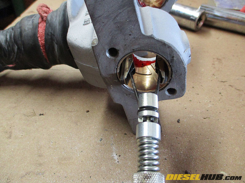
• The bushings must now be reamed out to fit the king pin itself. The ACDelco king pins are 1.792" diameter. Use a micrometer to measure the inside diameter of each bushing. Subtract the two and you'll have an idea of how much material needs to be removed.
• Technically, king pin bushings are supposed to be reamed out using a special reamer in a fixture that attaches to the knuckle and keeps the cutting bit perfectly perpendicular to the face of the bushing. Without keeping the reamer straight, there is a high risk of over-reaming and/or cutting the bushing crooked.
Case in point, we used a brake cylinder hone in place of a reamer. It's self-centering, very forgiving, and removes material slowly. It took about 10 minutes to hone each bushing to the proper inside diameter. Keep the stones well oiled while in use.
Ream/hone in small increments. Do NOT remove too much material. Frequently check with micrometer and kingpin. We recommend undersizing the bushing bore every so slightly so that the kingpin fits tight during assembly - if the kingpin fitment is loose, the bushing will have to be replaced.

• After the bushings have been reamed/honed to the proper diameter, carefully install the new grease seals on the inside of the top and bottom bushing slots (top plates seal the outside of the knuckle, wiper seals are used on the inside of the knuckle).
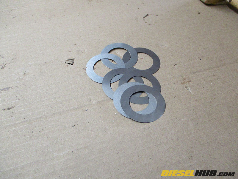
• The bearing located at the bottom of the knuckle must be shimmed to ensure a tight fit. A fair quantity of shims are included in the kit. All these mic'd out to 0.045 - 0.050".
• Mic the old shims you removed from the knuckle to get a baseline. The new bearing may not use the same shim thickness, but it makes a for a good starting place.
• Grease the bottom bushing then use the old kingpin to center the shims and bearings on the knuckle.
• Test fit the knuckle with the bottom bearing and shims in place (the old kingpin will keep them centered and give you leverage to move it into place). Check for excessive up-and-down slop and add shims as necessary until the knuckle/spindle assembly fits as tight as possible on the axle. The fitment of the steering knuckle must be tight with no up-and-down play.

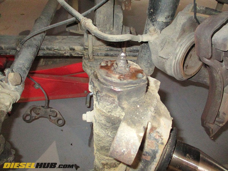
• Lube the upper bushing with grease, then drop a finger full of grease into the axle slot below the upper bushing. Slide (or lightly drive) the old king pin through the bottom pin and into the slot on the axle - this will help keep the knuckle centered while driving in the new pin from the top.
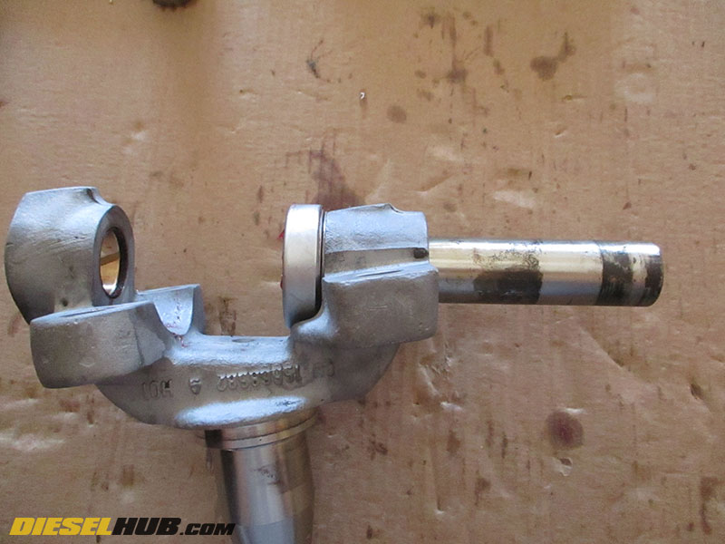
• Orient the king pin so that the ground down portion (where the retaining pin slides through) faces the wheel well, then drive the new king pin downwards with a brass or dead blow hammer. Note that the king pin is labeled "T" for top - the "T" must be facing upwards when the king pin is installed. The new king pin will drive out the old king pin being used to hold the knuckle in place, but don't let the old king pin fall out; we want it to remain the in the knuckle until the new king pin reaches the bottom bushing, thus the entire assembly stays aligned during the process.
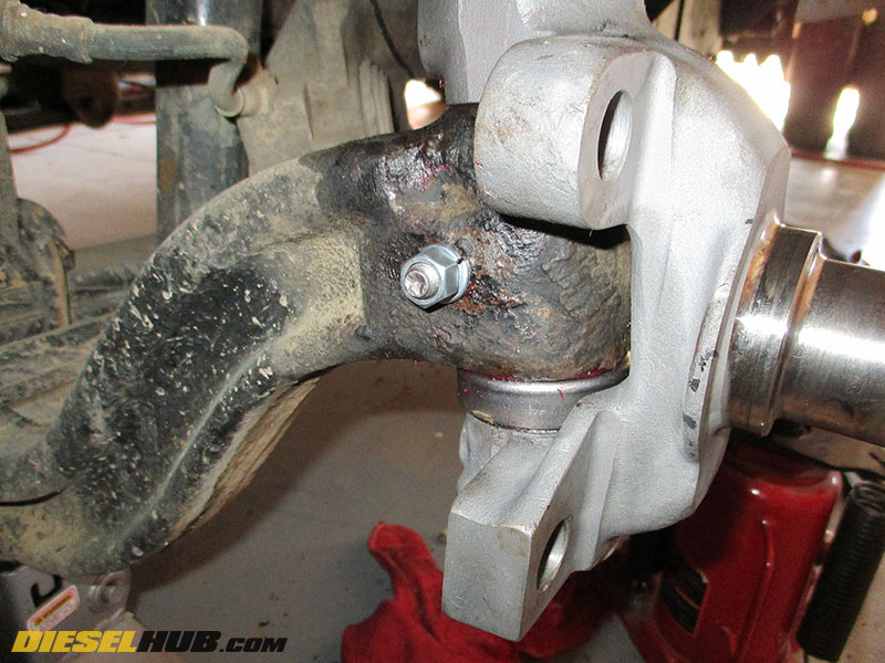
• Install the retaining pin through the hole in the axle. You may need to turn the knuckle left or right slightly to get the pin to line up with the slot in the king pin. If fitment of the king pin is tight, do not be alarmed. Snug down the retaining pin bolt until the lock washer is fully preloaded - no need to tighten excessively.
• Clean the top and bottom plates then make sure both Zerk fittings are clear. Reinstall both plates with new gaskets. Don't forget the brake caliper line and wheel speed sensor brackets that mount above the top plate.
• Grease both Zerk fittings and wipe off any excess.
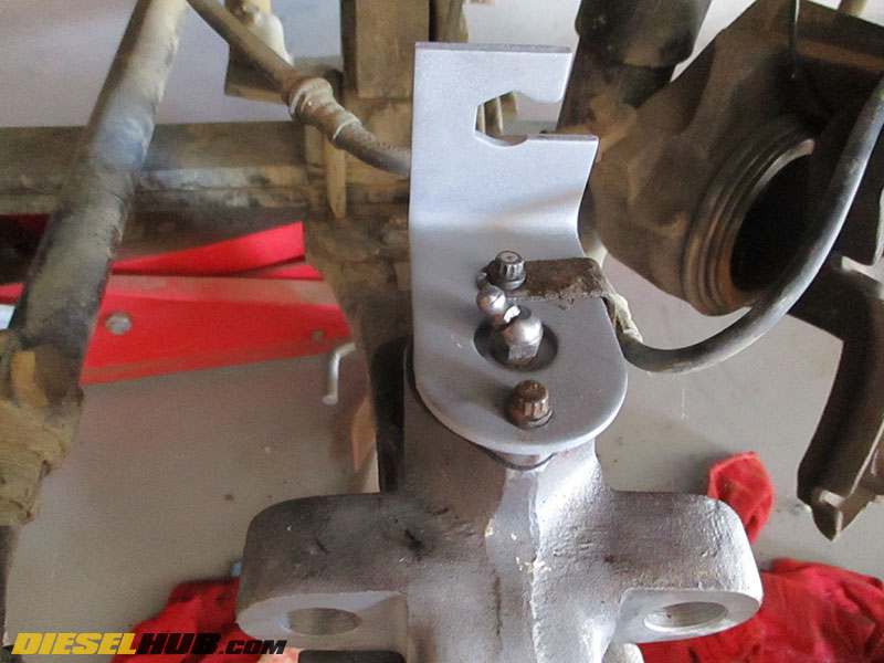
• Reinstall the steering bracket, brake caliper bracket, wheel speed sensor, and backing plate. Although there was no sign of threadlocker on the bolts when we removed them, we used a medium strength threadlocker on the 4 bolts securing the steering link and brake caliper bracket.
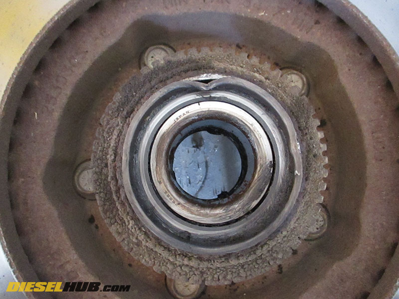
• Turn your attention to the wheel hub assembly. The outer wheel bearing will fall right out if it has not already. Do not lose the thrust washer that separates the wheel bearing and castle nut on the spindle.
• Remove the inner wheel seal. It is being replaced so do not be concerned with damaging it. In fact, it can be massaged out fairly easily after bending the flange in with a screwdriver in a few spots.

• The inner wheel bearing will now slide off the race with no resistance. Remove and discard it. Thoroughly clean the hub of all grease.
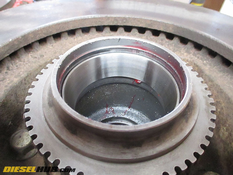
• Remove the inner and outer wheel bearing races. These are pressed tightly into the hub and can be difficult to remove. One easy method is to weld on the race in a few spots, then pound it out from the backside with a brass punch.
Note in the photo that the race was not heavily welded - just enough to heat it up. These were relatively easy to press out after welding a few small lines.
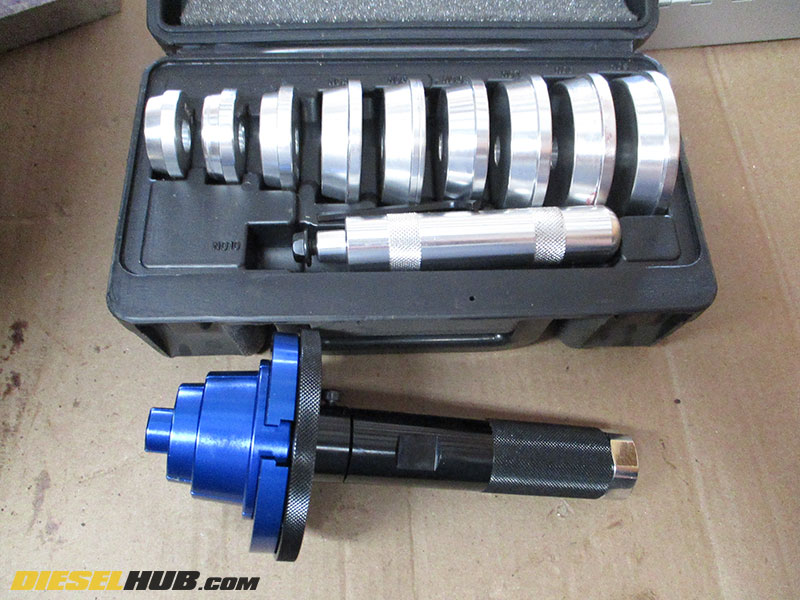
• Press in the new inner and outer bearing races. In the photo at left you'll find two examples of bearing race drivers. You'll need something similar to drive in the races.
The kit seen here with different sized drivers is OTC 4507. It's an excellent, high quality set that works flawlessly for driving in bearing races and wheel seals. Trying to seat races and seals without the proper tools may result in damage or improper installation.
• You'll know when the race is fully seated based on the feel in the hammer when you strike the driver. Tap it a few extra times for good measure, then inspect the race and ensure that it is completely and evenly seated.
• Once the new races are installed, thoroughly clean the hub assembly once more, including any grease that may have got on the brake rotor.
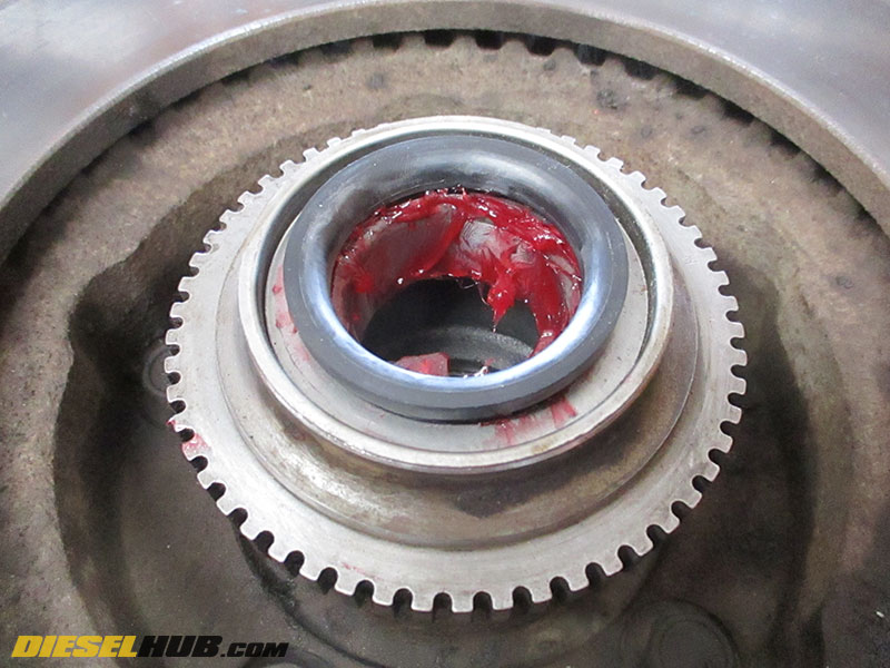
• Pack the inner and outer wheel bearings with high temperature bearing grease (recommend Timken GR224TUB).
• Once the inner bearing is packed, liberally glob it in grease then install it on the inner bearing race. Next, carefully install the inner wheel seal.

• Install the outer wheel bearing, followed by the thrust washer.
• Install and hand tighten the castle nut using a socket. Snug the nut up with a ratchet, then back the nut off. Once again hand tight the nut using a socket, then snug ever so slightly. Ideally, the nut should be tight enough to hold the bearings in place without placing an excessive compressive load on the bearings. Overloading the bearings will result in premature failure.
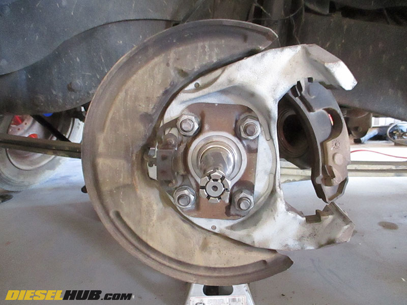
• Install cotter pin, tightening the castle nut to reach the nearest slot.
• Reinstall dust cap.
• Reinstall the brake caliper. It may take some patience to situate the caliper appropriately so that the slide can be reinstalled. Do not forget the Allen head retaining bolt.
• Reinstall the wheel. Torque lug nuts to 175 lb-ft.