6.6L Duramax Glow Plug System Overview
The 2006 to 2012 6.6L Duramax diesel utilizes a standard glow plug system featuring 8 individual glow plugs; 1 dedicated glow plug per cylinder. The system is somewhat unique, however, in that the glow plug control module supplies power to each glow plug individually by means of a dedicated transistor. Glow plug cycle times are managed by the ECM and are dependent on several factors, including ambient and engine coolant temperatures.
Although the glow plug module employs a dedicated transistor for each individual glow plug, all 8 glow plugs are activated simultaneously. The purpose of the glow plug system is to provide heat in the combustion chamber to ensure that fuel ignites completely at the top of the compression stroke. When an engine is in a cold state, particularly in extremely cold Winter conditions, fuel may not auto-ignite as intended or may not ignite completely. The glow plug positioned in each combustion chamber ensures that ignition takes place as it should when an engine is initially started, and they may be energized momentarily after the engine is started.
When one or more glow plugs and/or the glow controller malfunction or experience a fault, an engine may be difficult to start or run harshly immediately after starting. In certain environments, the engine may also require excessive cranking or may fail to start if the ambient temperature is low enough.
Glow Plug Module Programming
On LBZ and newer generations of the Duramax diesel, flowrates for each fuel injector are stored in the glow plug module as well as the ECM so that in the event there is a fault in ECM communication, this information can be retrieved from the memory of the glow plug module. Programming a new glow plug module consists of retrieving this information from the ECM and storing it in the memory of the module. This procedure requires a GM Tech 2 scan tool or equivalent electronic diagnostic device with this compatibility.
6.6L Duramax Glow Plug Module Parts List
| Part Description | Part Number(s) | Remarks |
| LBZ glow plug controller (2006 - 2007) | GM 98041624 | --- |
| LMM glow plug controller (2007 - 2010) | GM 98089571 | --- |
| LML glow plug controller (2011 - 2012) | GM 12652111 | --- |
| Glow plug (LBZ, LMM, LML) | ACDelco 9G | [1] |
[1] - Replaces ACDelco 61G, not compatible with 2004 - 2005 model year LLY.
6.6L Duramax Glow Plug Module Diagnostics & Troubleshooting
First and foremost, glow plug system faults should not be ignored, even if the engine seems to start with ease. Neglecting to determine the root cause of a glow plug fault can result in a swollen glow plug tip if the problem is causing a glow plug or series of glow plugs to over-cycle, or if current is continuously being supplied to a failed glow plug. Anytime the tip of a glow plug swells, it becomes difficult to remove and the risk of dropping the tip into the cylinder head increases. Problems should therefore be diagnosed and tended to promptly.
Glow plug system faults may occur in the controller, individual glow plugs, wiring harness/connectors, or a combination of these components. Common glow plug related DTCs (diagnostic trouble codes) include:
P0671 (cylinder 1 glow plug fault)
P0672 (cylinder 2 glow plug fault)
P0673 (cylinder 3 glow plug fault)
P0674 (cylinder 4 glow plug fault)
P0675 (cylinder 5 glow plug fault)
P0676 (cylinder 6 glow plug fault)
P0677 (cylinder 7 glow plug fault)
P0678 (cylinder 8 glow plug fault)
P0380 (glow plug circuit "A" malfunction)
P0382 (glow plug circuit "B" malfunction)
In an ideal world, a fault in the glow plug system should set a DTC; however, in the real world, you may not be so lucky. All 8 glow plugs are highly unlikely to fail simultaneously, thus DTCs referencing individual cylinders are typically the result of a glow plug failure and not a glow plug module malfunction. However, if a DTC or series of DTCs are set that identify a particular bank of glow plugs or glow plug circuit, the glow plug controller or wiring harness is the likely culprit. Glow plug system troubleshooting should always begin with a visual inspection of the glow plug controller, glow plugs, and all associated wiring, paying close attention to the electrical connectors and any possible chafe points. Note that removing the passenger and driver side inner fenders provides easy access to both banks of glow plugs.
Always check the glow plug ring terminals, flange nuts, and battery power supply wire for corrosion. Additionally, check the glow plug flange nut (securing the ring terminal to the top of the glow plug) for proper torque (44 in-lbs); something as simple as a loose or corroded connection can interrupt the entire glow plug system and cause a batch of DTCs to be set. Intermittent glow plug faults are often the result of a chaffed wire or poor connection.
Glow Plug Resistance Test (Ohm Test)
This basic test will quickly identify a faulty or "weak" glow plug. Set a multimeter to the resistance setting (often indicated by the Ohm sign, Greek letter Ω) and probe the terminal at the top of the glow plug with one test lead and a good ground (typically the base of the glow plug or nearby on the engine block) with the second lead. The resistance measured across each glow plug should be less than 1 Ω; any figure greater than 1 Ω indicates a faulty glow plug that needs to be replaced. For reference, a brand new ACDelco glow plug will read ~ 0.4 Ω using this test procedure. Note that the glow plugs need to remain OFF while measuring the resistance.
Glow Plug Module Test Procedure
Verify the following information to test for proper function of the glow plug module:
1) Verify that vehicle battery voltage is good; a low voltage condition may cause the glow plug module to operate erratically or cease to function.
2) Disconnect the battery voltage supply wire from the glow plug module (large gauge wire) and read the voltage between it and a good ground. If battery voltage is not detected, there is a bad connection (likely at the battery terminal) or a break in this circuit. If full battery voltage is measured at this connection, reinstall it to the glow plug module and continue below.
3) Check the voltage at each glow plug by measuring the voltage across the top of the glow plug terminal and a good ground while the glow plug preheat sequence is in progress (wait-to-start or glow plug preheat light is activated in the instrument cluster). If a single glow plug is not receiving power, inspect the wiring harness for an open circuit. If a bank of glow plugs is not receiving power or neither bank of glow plugs is receiving power, the glow plug module has likely failed.
How to Replace the Glow Plug Module on a 6.6L Duramax Diesel
Click any thumbnail to view fullsize, detailed image

• Disconnect both negative batteries cables.
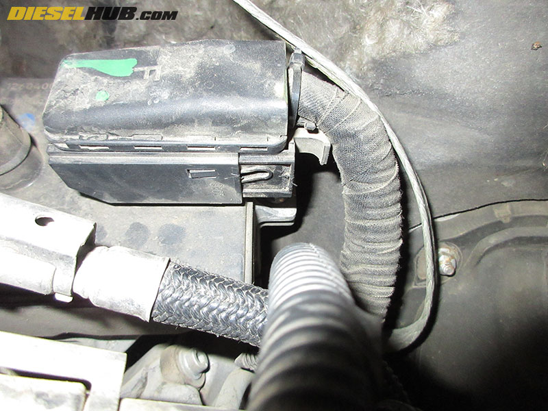
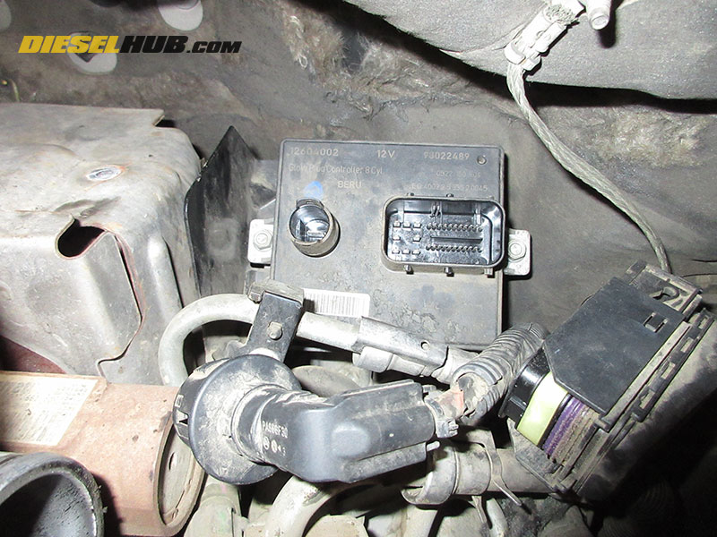
• Locate the glow plug controller to the driver side of the turbocharger near the firewall.
• Remove the glow plug power feed connector (round connector, left side of glow plug module) by pressing the two ridged segments of connector shell and pulling away from and out of the glow plug module.
• Remove the rectangular glow plug connector by first locating and releasing the slide lock. Slide the lock towards the driver side of the vehicle until the connector can be pulled off away from the controller.
• Remove the (2) bolts to the left and right of the glow plug controller using a 10 mm socket, then lift the glow plug controller off the bracket.
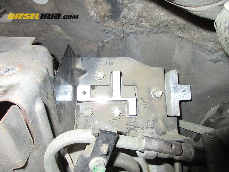
• Reinstallation of the glow plug controller is reverse - torque the (2) glow plug controller bolts to 89 in-lbs (inch pounds, NOT foot pounds).
