Applicable Models:
1992 - 2000 Chevy/GMC C/K 2500, 3500 trucks
1992 - 2002 Chevy/GMC C3500HD chassis cab
1994 - 1999 Chevy/GMC C/K 2500, 3500 Suburban
1994 - 1998 Chevy/GMC C/K 1500 trucks & Suburban
1994 - 2002 Chevy/GMC Vans (Express, Savana, G20, G2500, G30, G3500)
1995 - 1999 Chevy Tahoe
1994 - 1999 GMC Yukon
1994 - 1999 Chevy/GMC P30, P3500 chassis (motorhome and step van)
1994 - 2004 Hummer H1
Applicable Engine(s):
6.5L Detroit V-8 (turbocharged & naturally aspirated)
6.5 Diesel Fuel Filter Manager
The fuel filter housing on a 6.5 diesel is called the fuel manager, filter manager, or fuel filter manager. The fuel filter manager has three distinct roles: (1) filter fuel from the tank before it is delivered to the injection pump, (2) separate water from the fuel supply and allow it to settle in the bottom of the filter housing where it can be drained, and (3) create a means to bleed the fuel system following maintenance or repairs. A single 3/8 inch inlet fitting is incorporated into the housing at its rear (near firewall). The housing has (2) outlet fittings, one of which allows water to be drained from the bottom of the housing and the other providing filtered fuel to the injection pump. A bleed valve incorporated into the filter assembly allows air to be bled from the fuel system following service and repairs.

The water-in-fuel sensor is mounted through the passenger side of the housing while the fuel heater threads into its base. The filter housing mounts to the rear of the lower intake manifold via two large tabs. Both outlets, the drain and the injection pump supply, connect to 1/4 inch hoses that travel beneath the intake manifold. It is important to distinguish the outlet fittings as the passenger side port, labeled "DRAIN", provides a pathway to dispense water collected at the bottom portion of the housing while the driver side port, labeled "OUT", supplies filtered fuel. Fuel from the drain port is unfiltered and presents a serious concern if the injection pump feed hose was erroneously connected here.

The drain hose connects to a petcock mounted on a thermostat housing stud (figure 3 below). This fitting is used to drain water that collects in the bottom of the fuel bowl. When the "WATER IN FUEL" light or indicator becomes illuminated, it represents between 1/2 and 5/8 of an inch of water accumulated in the bowl. Attaching a hose to the drain valve and opening it while the engine is running allows this water to be expelled into a container without necessitating removal of the fuel filter. It is also used as a suitable port to test fuel pressure by connecting a pressure gauge and opening the valve.

6.5 Diesel Fuel Filter Housing Flow Path
Referencing figure 4 below, fuel is drawn from the fuel tank by the frame mounted lift pump and delivered to the inlet (#1) of the fuel filter housing at low pressure (5 to 7 psi). The inlet path immediately directs fuel down into the fuel heater bowl (#2) and then up the centrally positioned stand pipe (#3) where the fuel heating element is located. Fuel flows up the stand pipe until it reaches the head of the fuel filter assembly (#4) and is distributed into the outer area of the filter housing (between the filter element and housing) through a series of oblong shaped ports in the filter head (#5). At this stage, the fuel remains unfiltered and any water in the fuel will settle in the bottom of the filter housing.

Fuel is then forced through the filter element (#6) and into the outlet chamber (#7), finally exiting the filter housing at the outlet port. Filtered fuel from the outlet port is delivered to the injection pump, which is responsible for metering and delivering fuel to each injector at the correct pressure and time. Note there is a strainer mounted over the stand pipe that prevents debris from entering the outlet channel (#6) in the event a filter element should fail. Due to a sealing mechanism on the inside of the filter assembly (beginning at #3), fuel cannot enter the outlet channel/chamber without passing through the head of the filter assembly, into the housing, and through the filter element.
Fuel Heater
The fuel heater on a 6.5 diesel is mounted at the base of the fuel filter housing. It is comprised of a simple resistive heating element and internally integrated thermistor. This device receives vehicle power at anytime that the ignition switch is placed in the "ON" or "RUN" position. However, the thermistor acts as a self-regulating thermal switch that only completes the circuit when its temperature is below 46° F. Thus, while there's always power to the device when the engine is running or the glow plug pre-heat sequence is initiated, current only flows through the heating element at temperatures below 46° F.
The purpose of the fuel heater is to prevent fuel from gelling or crystallizing at cold temperatures, but it becomes a moot point if fuel has crystallized in the tank and cannot be drawn out by the lift pump. The fuel heater's role is more likely to ensure that fuel delivered to the injection pump remains below a viscosity threshold specified by the injection pump manufacturer, Stanadyne. Fuel delivered to the injection pump that is "thicker" than this specification could potentially cause accelerated wear and/or flawed operation.
Diagnosing the fuel heater is relatively simple with it removed. When the device is resting at a temperature greater than 46° F, there should be no continuity across its two wires (open circuit). At a resting temperature less than 46° F, there should be continuity across its two wires (closed circuit). Confirm that the circuit is open at room temperature and closed at a temperature below 46° F by placing the device in a freezer for 1 to 2 hours. If the device fails either test, it is not functioning properly.
The heater is the source of fuel leaks from two spots; at its o-ring seal and/or at the location that the wires pass into the device. New style fuel heaters feature a more resilient wire entry point than the original units. There are no commercially available fuel heater delete systems for the 6.5 diesel, likely due to the complexity of the mounting design. Furthermore, those who operate their vehicles in ambient temperatures below freezing should retain the fuel heater in proper working order.
Water-in-Fuel Sensor
The water-in-fuel sensor is mounted to the passenger side of the filter housing. Its probe protrudes through the housing approximately 1/2 inch above the bottom of the internal bowl where water droplets settle and accumulate. When the water level at the bottom of the bowl reaches the probe, a switch is activated and the ground circuit to the "WATER IN FUEL" light is completed, illuminating the light.
Repairing vs Replacing the Fuel Filter Housing
At the time this article was last updated (June 2024) it was approximately four times more expensive to rebuild the fuel filter housing than replace the entire unit as an assembly. In fact, just the fuel heater cost was 50% more than the entire assembly. The filter housing (GM 10226035) includes a a new fuel filter, filter retaining nut, filter strainer, water-in-fuel sensor, and fuel heater. It comes assembled and ready to install, no disassembly needed. It is therefore significantly more cost effective to replace the housing as an assembly than to replace either the water-in-fuel sensor or fuel heater individually (assuming you're replacing these with genuine GM parts).
While these prices are obviously subject to change, we highly recommend quoting any repairs against the cost to replace the entire fuel filter housing. Also take into consideration that anytime the filter housing is drained for repairs, the fuel filter element and fuel strainer must be replaced.
Fuel Filter Housing Parts List
| Part Description | Part Number | Remarks |
| Fuel filter housing assembly | GM 10226035 | [1] |
| Fuel filter | ACDelco TP1256 | [2] |
| Fuel filter retaining nut | GM 12511963 | [3] |
| Fuel filter strainer | Stanadyne 29244 | [4] |
| Water-in-fuel sensor | GM 12375515 | --- |
| Fuel heater | GM 12511964 | --- |
| Fuel hose, filter inlet | 3/8" ID fuel hose | [5] |
| Fuel hose, filter outlet to injection pump | GM 10229337 | [6] |
| Fuel hose, filter drain to petcock | 1/4" ID fuel hose | [5] |
[1] - Fuel filter housing assembly comes complete and ready to install with new filter, filter nut, filter strainer, water-in-fuel sensor, and fuel heater
[2] - Fuel filter must to be replaced anytime the fuel filter housing is removed or drained for repairs
[3] - Fuel filter retaining nut can be reused if not damaged; recommend replacing every 2 to 3 filter changes
[4] - Recommend fuel filter strainer be replaced anytime the filter element is replaced
[5] - Use common fuel hose rated for diesel fuel
[6] - Molded 1/4 inch hose installed between filter housing outlet and injection pump inlet
How to Remove the Fuel Filter Housing on a 6.5 Diesel
Click any thumbnail to view fullsize, detailed image

- Disconnect both negative battery cables.
- Locate the fuel filter housing mounted to the rear of the lower intake manifold.
- Slowly open the bleed valve on the top of the filter element canister to relieve any residual pressure in the fuel system.
- Remove the fuel filter retaining nut by rotating counter-clockwise (the retaining system is different on several popular aftermarket filters and the retaining device may be integrated into the head of the filter element assembly).

- Remove the fuel filter element by pulling upwards and subtly rocking it side-to-side.
- Remove and discard the filter element o-ring seal if it was left stuck to the top of the filter housing.
- Completely drain all fuel from the filter housing using a suction tool. Any fuel left in the bottom of the housing will leak out into the engine valley when the inlet/outlet hoses are removed.
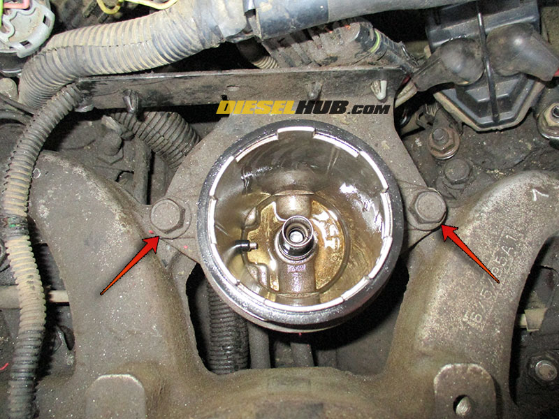
- Remove the (2) bolts securing the filter housing to the intake manifold mounting tabs with a 15 mm socket.
- Remove the bracket wrapping around the rear of the filter housing. Release and remove the series of electrical connector clips mounted through the holes in the bracket so that the bracket can be removed from the engine compartment and set aside.

- Tilt the filter housing towards the firewall to reveal the (2) outlet fittings at the base of the housing.
- Loosen and slide forward the clamps securing the (2) outlet hoses to the bottom of the filter housing.
- Remove the (2) outlet hoses from the fittings. If you are unable to maneuver the hoses at this time, this can be revisited after the inlet hose is removed.

- Maneuver the filter housing so that the inlet fitting is visible at the bottom-rear portion of the filter housing.
- Loosen the inlet hose clamp, then disconnect the inlet hose from the filter housing.
- Trace and disconnect the water-in-fuel sensor electrical connector (lower part of the passenger side of the filter housing).
- Trace and disconnect the fuel heater electrical connector (mounted to the bottom of the filter housing).
- Remove the fuel filter housing from the engine compartment.

- To remove the water-in-fuel sensor, remove the (2) fasteners with a 1/4 inch socket or wrench, then separate it from the housing.
- The water-in-fuel sensor is sealed with a single o-ring. Once removed, this o-ring will need to be replaced.

- The fuel heater is secured to the base of the housing by a retaining ring (similar to what secures the filter element at the top of the housing). Unthread the retaining ring to remove the fuel heater.
- The fuel heater is sealed with a single o-ring. Once removed, this o-ring will need to be replaced.

- Installation of the filter housing is reverse. Ensure to properly bleed the fuel system before attempting to start the engine; dry starting to prime may cause accelerated injection pump wear. Detailed fuel system priming information can be found here: bleeding air from the fuel system on a 6.5 diesel.
- Note - do NOT prefill the filter housing with fuel; unfiltered fuel will reach the injection pump.


Editor, Diesel Hub