Applicable Models:
2011 - 2024 Ford F-250, F-350, F-450, F-550 Super Duty
Applicable Engine(s):
6.7 Power Stroke V-8
Fan Clutch Operation
The 6.7 Power Stroke employs a variable speed viscous fan clutch controlled by a pulse width modulation (PWM) signal. Pulse width modulation uses a digital square wave output to command the functions of electromechanical devices. PWM signals are represented as a duty cycle, which is the ratio between the "on" and "off" states over a given period, most often specified as a percentage. For a more detailed dive into this subject, see: How pulse width modulation works.
The primary difference between an entirely mechanical fan clutch and a PWM fan clutch is in the control of fluid in the working area. A mechanical fan clutch relies on a thermostatic mechanism at the face of the clutch to control fluid flow into the working area. The engagement of the fan clutch is therefore dependent on the temperature of this thermostatic device and the environment around it. A PWM fan clutch, however, is PCM controlled and can be commanded on at any time based on the various inputs that represent the cooling needs of the engine under the current operating conditions.
The mode by the which the clutch effectively engages remains a product of the shear force created across the plates in the working area, and these forces are dependent on the amount of fluid allowed into this chamber. For the 6.7 Power Stroke fan clutch, the viscous drive actuator ultimately controls fluid flow into the working chamber. The viscous drive actuator is commanded by the PCM at a duty cycle between 0 and 100%, with 0% corresponding to minimal fluid in the working chamber and the lowest drag between the shear plates. 100% duty cycle therefore corresponds with maximum fluid flow into the working chamber and the greatest drag between the shear plates. As the drag between the shear plates increases, fan speed increases proportionally until the output speed is equal to that of the input speed.
6.7 Power Stroke Fan Clutch Diagnostics
A fan clutch that it is mechanically stuck or internally binding will not set a DTC nor illuminate the MIL. When the PCM performs a self-test, it only verifies that the fan speed is correct at 100% duty cycle. A DTC is set if the measured fan speed is less than expected under this condition. DTCs will also trigger for open or short circuits related to the viscous drive actuator, but there is no such test for a fan clutch that is running all the time.
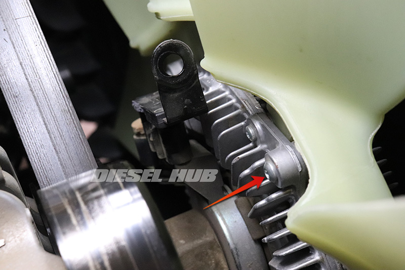
It is very obvious when the fan is running on a 6.7 Power Stroke, especially during acceleration as it can be quite noisy. Additionally, you'll likely feel the additional drag that the engine is having to overcome. There are several ways of diagnosing fan clutch related problems and identifying a fan clutch that is mechanically bound. The OBD-II system incorporates three PIDs and two special tests corresponding to fan speed and fan clutch duty cycle. A hall effect type sensor mounted between the attachment nut and body of the fan clutch provides a real-time fan speed reading to the PCM.
- Cooling Fan Duty Cycle - Current duty cycle commanded to the viscous drive actuator, given as a percentage.
- Cooling Fan Speed - Current measured speed of the cooling fan in RPM.
- Desired Cooling Fan Speed - Current fan speed that is desired by the powertrain control module in RPM.
- Viscous Fan Pulse Width Modulated Control Test - Allows manual control of the PWM duty cycle; operator can increase and decrease the fan duty cycle while monitoring actual fan speed. If the fan speed does not increase or decrease with corresponding duty cycle changes, there is a problem with this system.
- Fan Speed Desired Test - Allows manual control of the desired fan speed. If the fan speed does not increase or decrease with the corresponding commands, there is a problem with this system.
Note that the PID names and how their accessed is going to be determined by the diagnostic instrument being used and may differ based on vehicle model year. Additionally, the fan clutch does not necessarily respond to PWM signal changes immediately; it can take up to 2 minutes for the clutch to reach an equilibrium state after giving commands. Figure 1 below identifies setting up the appropriate PIDs on FORScan for a 2021 model year Super Duty. These tests are most accurately performed after the vehicle has warmed up for several minutes, ensuring it is not currently performing the self-test.

The diagnostic theory here is quite simple - compare what the cooling fan is doing to what it is supposed to be doing. If the PCM is not commanding the fan clutch to engage, this should be represented in the current speed of the fan. If the PCM is commanding the fan clutch to engage, the fan should be running accordingly. It is important to note that the fan speed will never be 0 RPM when the engine is running. By virtue of design, there will always be some drag in the clutch mechanism and the fan will always be rotating. Although it should go without saying, never attempt to touch a cooling fan with the engine running - this will result in severe injury.
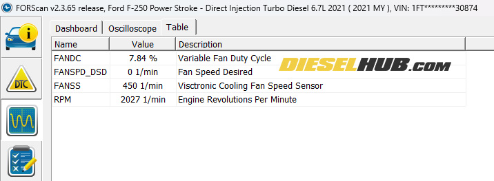
Another noteworthy observation is that the cooling fan is overdriven with regard to crankshaft speed and therefore when the fan clutch is in the fully locked position, it will rotate at a higher RPM than the engine. The overdriven ratio is approximately 1.42 to 1 - at 100% duty cycle, the fan will spin nearly 1-1/2 times to each engine rotation. Figures 2 and 3 below correspond to readings of a fan clutch that is mechanically stuck.

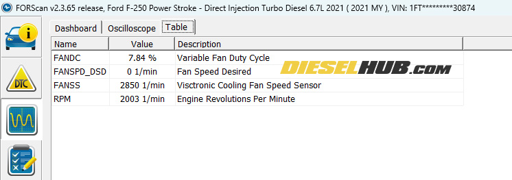
The data clearly indicates that there is an issue with this fan clutch - the fan speed desired by the PCM is 0 but the cooling fan is rotating at 850 rpm at idle speed and 2,850 rpm at an engine speed of 2,000 rpm. Although we previously suspected this to be the problem based on a test drive, these readings support the hypothesis. Figures 4 and 5 below depict a normally functioning fan clutch (same vehicle, post-replacement data).

Note that the cooling fan is spinning at 325 rpm at idle. As previously mentioned, there are absolutely no operating conditions where the cooling fan speed will be zero as long as the engine is running - the fan will always spin to some degree do to residual drag in the working chamber of the clutch mechanism. However, notice that the fan speed only increased by 125 rpm when the engine speed was brought up to 2,000 rpm; this fan clutch is performing as expected.
Applicable Parts List
| Part Description & Application | Part Number |
|---|---|
| 2011 - 2014 Super Duty Fan Clutch | Motorcraft YB3188 |
| 2015 - 2019 Super Duty Fan Clutch (built before 7/9/2018) | Motorcraft YB3189 |
| 2019 Super Duty Fan Clutch (built on/after 7/9/2018) | Motorcraft YB3246 |
| 2020 - 2022 Super Duty Fan Clutch, single rear wheel truck | Motorcraft YB3288 |
| 2020 - 2022 Super Duty Fan Clutch, dual rear wheel truck | Motorcraft YB3291 |
| 2023 - 2024 Super Duty Fan Clutch, single rear wheel truck | Motorcraft YB3307 |
| 2023 - 2024 Super Duty Fan Clutch, dual rear wheel truck | Motorcraft YB3308 |
| Fan clutch wrench | Gearwrench 3473 |
| Fan clutch pulley holder | Gearwrench 3900 |
How to Replace the Fan Clutch on a 6.7 Power Stroke Engine
Click any thumbnail to view fullsize, detailed image

- Disconnect both negative cables.

- Remove the intake duct between the air filter box and turbocharger compressor inlet tube. The hose clamps require a 7 mm socket.
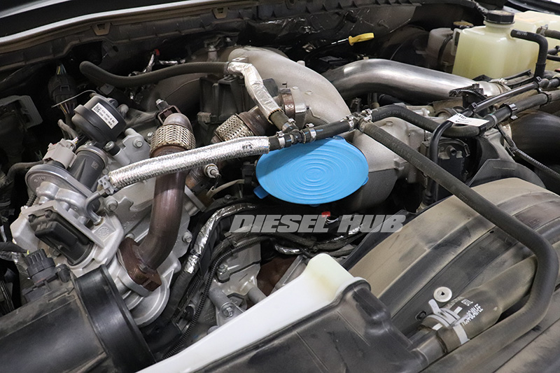
- Cover the turbocharger inlet tube to prevent dust, debris, and/or foreign objects from infiltrating the system.
- Locate the fan clutch connector.
- Pull or work the gray tab on the connector upwards. A small flathead screwdriver or 90 degree pick works well, but be sure to pry the tab incrementally from both sides to prevent damage.

- Once the gray tab has been raised, squeeze the connector (pinch the gray tab against the body of the connector) and pull upwards while wiggling side-to-side to work the connector loose.
- Position the connector aside in a safe place.

- Use a body clip removal tool to pry and release the clip securing the connector wiring to the fan clutch bridge.
- If the tab on the bridge should break, wait until the old fan clutch is removed and revisit this step; there will be significantly more room to separate the two pieces without damaging the clip itself.

- Remove the bolt securing the fan clutch bridge to the front cover with a 13 mm socket.
- Reposition the fan clutch connector bridge so that it is out of the way.
- Disconnect the fan from the fan clutch by backing off the (4) bolts with a TP-27 Torx Plus driver/socket. You will need to catch the small flange nuts on the backside of each screw; use one hand to loosen the bolt and two fingers to catch the nuts on the backside. This is a very tedious task and it is difficult to reach behind the fan. Wear long sleeves and gloves as the fan blades are quite sharp.
- Once one nut has been recovered, rotate the fan to reposition to the next bolt. Do not remove the smaller and shorter Torx headed fasteners as they mount the two halves of the fan clutch together.

- When the fan clutch has been separated from the cooling fan, gently position the fan in the void between the radiator and fan shroud so that it will not interfere with removal of the fan clutch.

- Familiarize yourself with the fan clutch tools - you will need a 47 mm fan clutch wrench and a fan clutch pulley holder.
- Note that the fan clutch pulley holder has (2) removable pins; these pins will be inserted into the corresponding holes in the drive pulley to hold it in place while the wrench is used to break the fan clutch nut loose.
- The fan clutch wrench features a 1/2 inch drive extrusion so that a breaker bar can be used for addition leverage.

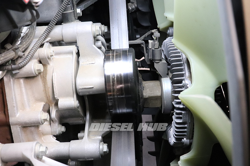
- Install the pulley holder by placing the pins into two corresponding holes. Note that the pins on most common pulley holders may be smaller than the holes in the pulley on a 6.7 Power Stroke, but should secure the pulley nonetheless.
- While holding the pulley tightly, use the fan clutch wrench to break the fan clutch nut loose. From the front of the truck (leaning over the radiator), rotate counterclockwise to loosen.

- Once the nut has been loosened, support the fan clutch and continue to rotate counterclockwise until it is free.
- Remove the fan clutch from the engine compartment.

- Install the new fan clutch in reverse order.
- Tighten snug using the fan clutch wrench while keeping the pulley secure.

- Reinstall the fan. Instead of tightening the Torx headed fasteners, install the nuts on the backside and tighten snug with a 10 mm socket.
- Install the fan clutch connector bridge with the front cover bolt.
- Install the fan clutch connector, pushing the gray tab downwards to lock it in place.
- Reinstall the air intake tube and reconnect the negative battery cables.
- Start the engine and test for proper operation (revisit diagnostic procedures). Note under certain conditions it is normal for the fan to run continuously for several minutes after startup, so the engine may need to be warmed up before testing.

