The primary function of the a fan clutch is to regulate the speed of the engine cooling fan and minimize parasitic drag on the engine when the fan is not needed. A fan that rotates with the engine at all times consumes a significant amount of engine power and reduces fuel economy. You may note that an engine seems sluggish when the cooling fan is activated - this is because it takes additional engine power to operate the fan. Additionally, the cooling fan is designed to supplement airflow in an on-demand basis.
Under most driving conditions, it is not necessary to run the cooling fan at all times to regulate engine coolant temperature. Disconnecting the fan from the engine when it is not needed therefore improves engine efficiency. When the engine temperature exceeds a certain threshold, the fan clutch engages to provide additional airflow across the radiator fins.
Types of Engine Cooling Fans
Engine cooling fans come in several types, including viscous, electric, and fixed. Electric fans do not require a clutch and instead are only powered on when needed. They function entirely independent of engine rotation, so an electric cooling fan can technically run even when the engine is off. Fixed cooling fans rotate at a speed relative to the engine, based on the ratio between the crankshaft and fan pulleys. These are entirely uncommon on modern vehicles due to the inherent inefficiency.
Viscous type cooling fans are by far the most common system used These employ a viscous fan clutch that is regulated by an integral thermal-mechanical device or a form of electrical actuation, such as pulse width modulation (PWM). This design is largely efficient because the fan is engaged when there is a demand for supplemental airflow, but drag on the engine is minimized when the fan clutch disengages. Additionally, the fan speed is variable between ~ 0 and the maximum possible speed relative to engine RPM (most fans are overdriven relative to crankshaft speed).
How a Viscous Fan Clutch Works
A basic viscous fan clutch can be broken down into five key components:
- Clutch housing with integral shear plates on both internal surfaces - these are the "driven" shear plates
- Centrally located shear plate positioned between those integrated into the clutch housing - this is the "drive" shear plate
- A shaft connecting the center shear plate to the accessory drive pulley - the shaft and drive plate will always spin at a speed relative to engine RPM
- A bearing that supports the drive shaft and allows it and the drive plate to rotate independently of the clutch housing
- A thermostatic device that regulates the flow of a viscous fluid into and out of the working chambers of the fan clutch
Centrifugal force, the viscous fluid, and the corresponding shear force generated between the rotating plates are fundamentally responsible for the rotational speed of the fan relative to the clutch input speed. The thermostatic device regulates the flow of a viscous fluid into and out of a reservoir - as the volume of fluid present between the shear plates increases, the shear force and fan speed increase proportionately. When the thermostatic device closes, centrifugal force brings the fluid to passages in the outer section of the clutch housing where it is ultimately returned to the reservoir. The process repeats as the thermostatic device perpetually opens and closes in response to temperature fluctuations.
Shear Plates & the Working Chamber
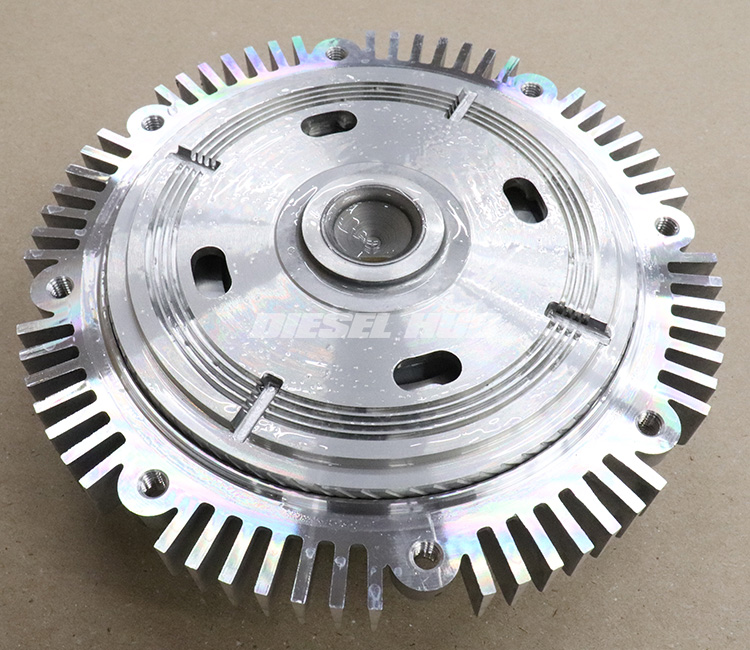
Collectively, the shear plates inside the fan clutch make up the actual clutching mechanism. The drive portion of the clutch is positioned centrally and spins at engine speed at all times. Since the fan clutch is ultimately rotated by a crankshaft pulley, it technically rotates at a speed above (over-driven) or below (under-driven) that of the actual engine RPM depending on the pulley ratio (ratio between the crankshaft and fan clutch pulley diameters). To keep things simple, we'll continue to imagine that the pulley ratio is 1:1 and the drive portion of the fan clutch is rotating at engine speed. Figure 1 below shows the drive portion of a typical viscous fan clutch with one half of the housing removed.
The driven portion of the fan clutch is integrated into the housing itself and also attaches to the fan blade assembly. It spins at a speed that is dependent on the amount of viscous fluid traversing across the shear plates. The area between the two driven clutch faces is the working chamber. As the amount of fluid in the working chamber increases, the shear force between the drive and driven plates increases proportionately. Figure 2 below shows a close up view of the drive and driven shear plates. Note the coupled grooves machined into the faces and the close fitment.
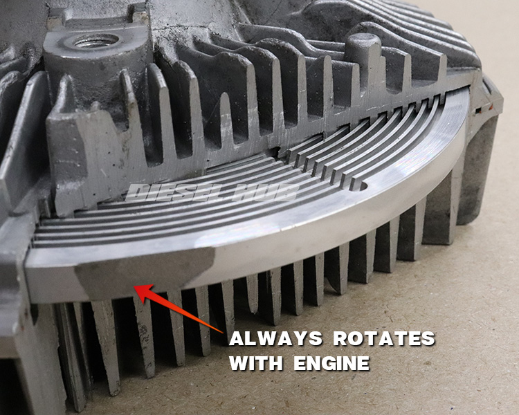
As fluid travel across this network of machined grooves due to centrifugal force, a shear force is generated against the plates that results in the clutching action; the greater the shear force, the greater the fan (output) speed. Centrifugal force also forces the fluid to the outside of the working chamber where it returns to the reservoir through a series of passages. If the thermostatic metering device remains open, this fluid re-enters the working chamber. If the metering devices closes, the fluid remains in the reservoir.
Viscous Fluid Metering Device
In order to prevent the fan from rotating at all times there must be a metering device integrated into the clutch that controls the flow of fluid between a reservoir and the working chamber. A modern PWM fan clutch performs this task my means of an electric actuator. The benefit with these fan clutches is that the powertrain/engine control module can command the fan on based on coolant or oil temperature sensor inputs.
A typical mechanical fan clutch is not computer controlled and instead uses an air temperature sensing bi-metal spring to actuate the metering device. Noting that the fan clutch is mounted between the radiator and front for the engine, the spring expands as it absorbs heat from the clutch housing and air flowing around it. One side of the spiral shaped spring is fixed to the housing such that a rotating action occurs as it expands and contracts. The center of the spiral is attached to a shaft that opens and closes a valve between the reservoir and working chamber. Figure 3 below indicates the location of this type of thermostatic device and the motion that occurs as the spring expands and contracts.
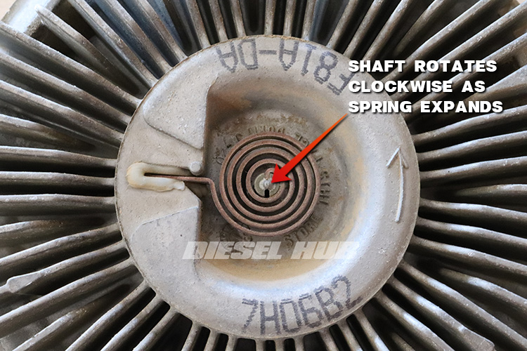
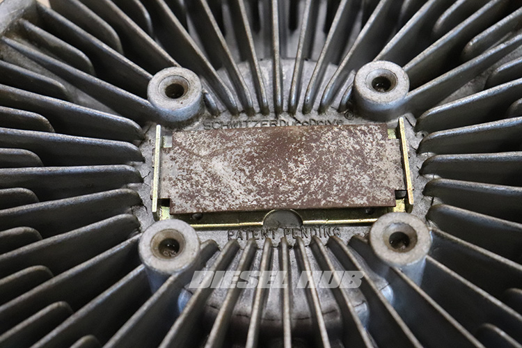
Figure 4 (below) shows an alternative to the radial device. Instead of rotating an actuator, this rectangular strip expands at a higher rate than the fixture that it is secured to. This forces it to bow (turn "U" shaped), changing the linear position of a protruding actuator rod behind it. Case-in-point, although the rotating mechanism seen in figure 3 is very common, other control types do exist.
Electric Fan Clutches
Electronic fan clutches are widely common in modern vehicles. These come in two sub-types, electromagnetic and pulse width modulated (PWM). In an electromagnetic fan clutch the clutch is engaged when voltage is applied to an electromagnet, subsequently closing the gap between friction plates on the drive and driven sides of the clutch. The operation is on par with that of a typical AC compressor - the clutch is either engaged or disengaged with no in-between or form of speed control relative to engine speed. These are also not a viscous type fan clutch and are more commonly found in large displacement tractor engines.
Pulse width modulated fan clutches are more common on today's light and medium duty vehicles. These are a variable speed viscous type clutch, but the thermostatic device is controlled by an electronic actuator. The PCM/ECM therefore ultimately controls the flow of fluid between the shear plates by means of a PWM signal. A speed sensor is typically integrated into these clutches so that the PCM/ECM receives a real-time reading of the actual fan speed. The fan speed is increased or decreased as necessary based on the instantaneous cooling needs of the engine (correlating with ambient, engine, and oil temperatures).
Causes of Fan Clutch Failures
Fan clutch failures typically result from a loss of fluid, overheating, or a combination of both. Minute leaks can develop between the housings that allows the fluid to escape under intense centrifugal force. These often go unnoticed because there are no obvious signs of a leak when the clutch is stationary. Over many thousands of miles and tens of millions of rotations, the viscous fluid is depleted. When this occurs the fan clutch will display very little resistance when spun by hand.
Excessive heat build up in the housing and between the shear plates can also cause a fan clutch to fail. One or more of the aluminum components can deform, seize, or bind and render the clutch defective. When spun by hand, a seized fan clutch shows absolute resistance and wants to spin the input shaft pulley. It is possible that a loss of fluid can cause the internal temperature of the fan clutch to increase, ultimately leading to its demise. A bearing or other mechanical component can also wear, causing the shear plates to come into contact with one another. The intense heat generated by friction between the two metal surfaces could therefore cause them to seize.
Damage to the thermostatic device, whether it be mechanical or electrically actuated, would also render a fan clutch as defective. These devices are not generally serviceable and fan clutches are replaced as a complete assembly.
Basic Fan Clutch Diagnostics
First and foremost, never attempt to touch a spinning fan - the fan blades rotate at relatively high speeds and injury or even dismemberment is likely. Diagnosing a viscous cooling fan clutch is relatively simple and the steps are broken down in the list below:
- With the engine off, take a quick visual inspection - if there are obvious signs of a fluid leak or the thermostatic spring is broken, replace the fan clutch.
- With the engine off, rotate the fan by hand. It should spin freely, but with light to moderate resistance. This test proves that the fan clutch is not mechanically bound. If the fan does not spin, spins with extremely high resistance, and wants to spin the accessory drive pulley, it is bound and needs to be replaced.
- In the event an engine begins to overheat, immediately ask yourself whether or not the fan clutch had kicked on. When running at full speed, the sound of the cooling fan is exceedingly obvious and engine power often feels marginally reduced. If the engine coolant temperature is getting high enough to cause indications of overheating (steam, instrument cluster warnings, high coolant temperature gauge reading), the fan clutch should be running at full speed. If it did not kick on, it's time to replace it.
- Pulse width modulated fan clutches are further diagnosed with an electronic diagnostic tool (scantool). Since they return a fan speed reading, you'll want to manually command the actuator duty cycle and verify that the fan speed increases proportionally. If the fan speed does not respond to the commands, the fan clutch should be replaced.

