A fault in the glow plug system is likely to produce a hard start, long crank, or no start condition with visible black or white smoke emitting from the tailpipe. In the event of a hard start/long crank condition, the engine may run rough upon initial startup and/or emit excessive smoke for a brief period. A quick check to see if the glow plugs are being cycled is to measure the current draw on the positive battery cable that connects to the starter relay on the passenger side fender. There should be approximately 120 to 150 amps of current draw during the preheat cycle. If there is significantly more or less current draw, it might be time to Ohm out the glow plugs. If there is little to no current draw, power is not being delivered to the glow plugs.
Glow Plug System Overview
The glow plug system on a 7.3 Power Stroke consists of a glow plug relay or controller, (8) individual glow plugs, and the associated wiring. All vehicles except late 1999 to 2003 models with California emissions rely on a simple PCM commanded relay to activate the glow plugs during the wait-to-start sequence. Late 1999 and newer vehicles equipped with the CA emissions package utilize a more complex glow plug control module (GPCM). The GPCM serves the same primary function as the relay, but offers more sophisticated diagnostic and system monitor functions.
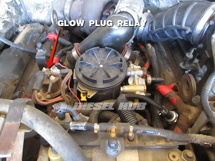
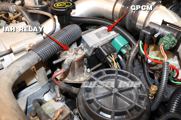
On 1994 to 1999 model year engines, the glow plug relay is mounted atop a bracket positioned towards the passenger side of the fuel filter housing (figure 1 above). Ford added an intake air heater (IAH) as part of the 1999 mid-model year update, which moved the glow plug relay towards the rear of the engine several inches and positioned the IAH relay on the same bracket, but towards the front of the engine. The IAH and glow plug relays are largely indistinguishable but serve separate functions - do not confuse the two components during diagnostics. On engines equipped with a GPCM, the module is mounted where the relay would normally be positioned (figure 2 below).
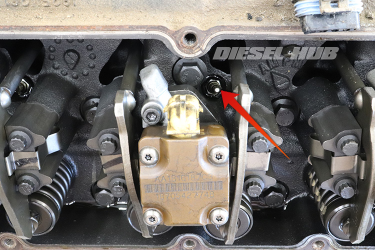
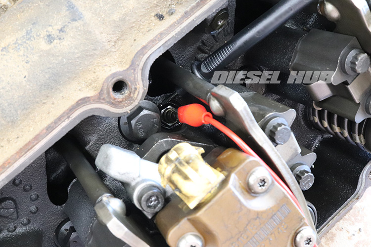
There is a single glow plug protruding through the cylinder head and into each combustion chamber for a total of (8) individual glow plugs. The glow plugs are accessed through the top of the cylinder head next to each fuel injector (figure 3 below) after the valve covers are removed. The glow plug wiring harness is an incorporated part of the fuel injector under valve cover harness (UVCH), which uses a pass-through connector formed into each valve cover gasket to connect the UVCH to the engine wiring harness. This pass-through connector is a known source of connectivity issues that can plague both the glow plug and fuel injection systems.
The glow plugs themselves are simple, self-limiting resistive heating elements. Their purpose is to heat the combustion chambers and incoming air charge to permit auto-ignition at the time of injection. This aids in starting, but also contributes to cleaner and more efficient combustion events during engine startup and for a brief period after the engine has begun to run. The glow plug cycle time (heating time) is determined and commanded by the PCM based on engine oil temperature (EOT) and barometric pressure (BARO) readings. A brief post-heat sequence may be commanded after the engine is running, also depending on these conditions.
Diagnostic Sequence
Note that some of the following subroutines can be performed out of the listed orders or disregarded depending on the actual symptoms, but these steps ultimately outline the process of troubleshooting a fault in the glow plug system without any additional facts; the problem lies somewhere between the items in this page. Additionally, do not assume that a certain component cannot be the problem because it was recently replaced, isn't that old, etc - a thorough diagnosis saves both time and money in the long run. Moderate competency with a digital multimeter is required to perform these diagnostic tests.
Also take note of the symptoms that are present. A no start, hard start, or long crank condition with no visible white or black smoke indicates the engine is not getting fuel. The fuel system operates entirely independent of the glow plug system and the fuel injectors will fire whether the glow plug system is working or not. If the engine is not getting fuel, redirect the diagnostic efforts to that system. If the engine cranks slowly, address this issue first. Even with a properly functioning glow plug system, the 7.3 Power Stroke has a minimum cranking speed required to start normally.
Verify Battery Condition, Terminals, & Ground Connections
The glow plug system initially draws 150 or more amps when it is switched on. Verify that the batteries have good voltage (ideally 12.5 to 12.7 for a fully charged, reasonably good battery) and that the battery terminals and ground connections are properly secured. If the engine cranks over at normal speed, the battery should have sufficient charge to operate the glow plug system and the connections should be adequate. If battery voltage is below 12.5 and engine cranks slowly, fully charge batteries.
Connect a scantool to the vehicle's OBD-II system and read any DTCs. For engines equipped with a relay, a P0380 indicates a short or open in the glow plug relay coil circuit - refer to glow plug relay test procedures below. If the engine is equipped with a GPCM, a range of DTCs can be set to help narrow down the culprit - refer to GPCM DTCs & test procedures below.
Test the Glow Plug Relay
If the relay has a protective cover, remove it and begin by visually inspecting and wiggling each connection. Repair any loose, corroded, or damaged connections before continuing. On 1999 and newer engines, do not confuse it with the IAH relay, which is positioned closer to the front of the engine than the glow plug relay.
Acquaint yourself with the terminal layout of the glow plug relay, as identified in figure 4 below. It is possible for the terminals to be installed opposite the OEM arrangement (in a prior repair, for example) and the relay will still function properly as nothing is polarity dependent. The pair of small terminals represent the coil component of the relay. When voltage is applied across the two terminals (battery voltage "B+" on one side, ground on the other) the switch will be activated and there will be continuity between the pair of larger terminals.
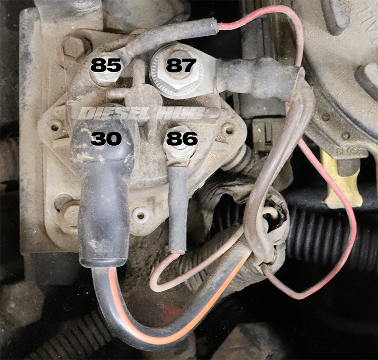
- Terminal 86 - orange wire (typically), hot (B+) at all times key is in the "RUN" or "CRANK" positions
- Terminal 85 - red wire, PCM completes the ground to this wire when the glow plug system is commanded "ON"
- Terminal 30 - large black wire with orange stripes, hot (B+) at all times; splits into two fusible links and draws power from the starter relay battery + terminal (also hot at all times)
- Terminal 87 - two brown wires, positive output to glow plugs; each brown wire supplies battery + to one bank of glow plugs when the relay is switched "ON"
The PCM commands the glow plug system "ON" by completing the ground at terminal 85 from figure 4. Terminal 86 therefore needs to have battery positive voltage when the key is cycled to the "RUN" position.
Note that the relay makes a very distinct clicking sound when it the coil is energized and de-energized; the absent of this sound during the preheat sequence is an early indication that the relay is not switching to the "ON" state. If the relay clicks repeatedly, thoroughly test the system to verify that it is a relay malfunction (it likely is). If the glow plug relay is energizing but won't de-energized, look for a short to ground between terminal 85 and the PCM.
Initially verify the function of the relay by checking the voltage between terminal 30 and ground. Battery voltage should be present at all times. If there is no voltage between terminal 30 and ground, check connections and fusible links at the starter relay. To check fusible links, disconnect the ring terminals at the starter relay and glow plug relay, when check for continuity between both ends of the wire. If there is no continuity, this circuit is open and the fusible links should be replaced.
Next, verify that the relay is switching properly by measuring the voltage between terminal 87 (pair of brown wires) and ground immediately after switching the key to the "RUN" position. If battery voltage is present here during the preheat sequence, it has been proven that the glow plug relay is functioning properly.
If the glow plug relay is not switching (no power going to the 87 during the glow plug preheat sequence), verify the relay coil circuit by measuring the voltage across terminals 85 and 86 during the glow plug preheat sequence. If voltage is present, this circuit is functioning correctly. It can therefore be determined that the relay is malfunctioning if the coil circuit is receiving power but the relay is not switching (no power to terminal 87).
The relay coil circuit can also be tested by disconnecting the terminals on both sides and measuring the resistance across the two relay terminals. Resistance should read between 1 and 8 Ohms (Ω). If the resistance reading is not within spec, the relay should be replaced.
If the coil circuit does not have voltage across the two terminals, verify that terminal 86 reads battery voltage to ground with the key in the "RUN" position. If no voltage is present, search for an open in this circuit. If 86 reads battery voltage but there is no voltage across the coil circuit during the preheat sequence, look for an open between the PCM and terminal 85 (red wire).
Test the GPCM
Use a diagnostic tool (scantool) to perform a KOEO self test and read any DTCs. A fault in the glow plug system can result in one or more of the following DTCs to be set:
- P0670 - Glow plug control module short or open circuit (pin 8, green connector)
- P0671 - glow plug #1 fault
- P0672 - glow plug #2 fault
- P0673 - glow plug #3 fault
- P0674 - glow plug #4 fault
- P0675 - glow plug #5 fault
- P0676 - glow plug #6 fault
- P0677 - glow plug #7 fault
- P0678 - glow plug # 8 fault
- P0683 - Glow plug control module diagnostic communication line short or open circuit (pin 9, green connector)
The DTC or combination of DTCs should be used as guidance. For example, if a single P0671-P0678 DTC is present than the identified glow plug or glow plug circuit should be investigated. The first step in this instance would be to measure the resistance across that individual glow plug. If the glow plug resistance is within spec, verify continuity through the appropriate terminal in the green or black GPCM connector and the actual glow plug connector. If continuity is present, measure resistance in this circuit. No continuity is indicative of an open circuit while high resistance likely points to a poor connection somewhere in the circuit.
If DTCs are grouped as one entire bank of glow plugs (1, 3, 5, 7 on the passenger side, 2, 4, 6, 8 on the driver side) investigate for a poor connection at the GPCM, UVCH, or a GPCM failure. It is highly unlikely that an entire bank of glow plugs would fail all at once.
When an entire bank of glow plugs experiences a fault, it is likely a poor connection or GPCM related problem. Isolating the problem can be done by performing continuity and resistance checks between the various connections until the culprit is found. If all the wiring is found to be secure, the GPCM may have failed. For P0670 and P0683 trouble codes, verify that the GPCM connectors are tightly secured and in good condition.
If the wiring harness is suspected to have an open, short, or poor connection between the GPCM connector and the glow plug/UVCH connector, disconnect the black and green connectors from the GPCM. A multimeter can be used to test resistance in each individual circuit. Refer to the connector pinouts in figure 5 (below) and probe the appropriate connections.
| Pin Number | Green Connector | Black Connector |
|---|---|---|
| 1 | Output to glow plug #5 | Output to glow plug #6 |
| 2 | Output to glow plug #7 | Output to glow plug #8 |
| 3 | Battery positive input (V+) | Battery positive input (V+) |
| 6 | Output to glow plug #1 | Output to glow plug #2 |
| 7 | Output to glow plug #3 | Output to glow plug #4 |
| 8 | PCM control circuit | N/A - no terminal |
| 9 | GPCM diagnostic communication output | Vehicle power relay input |
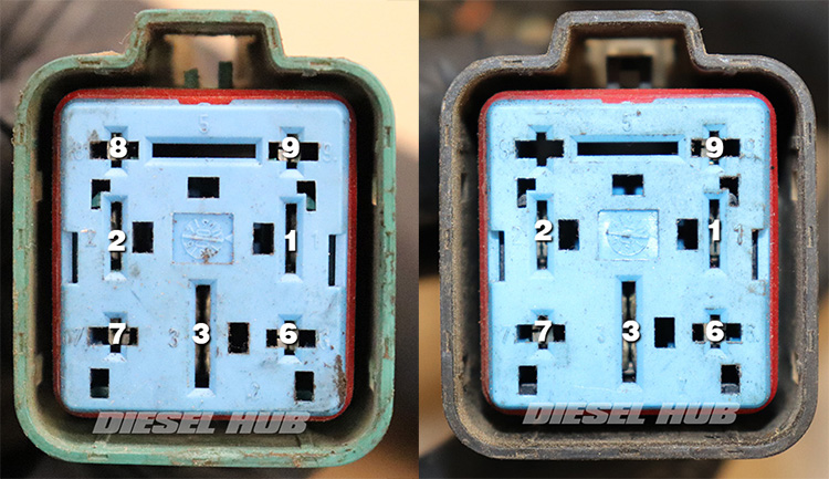
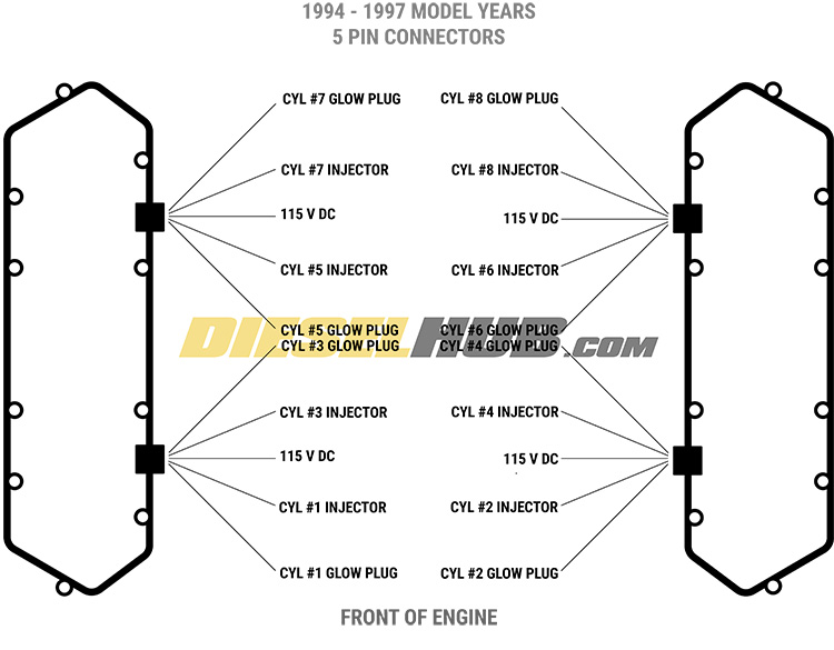
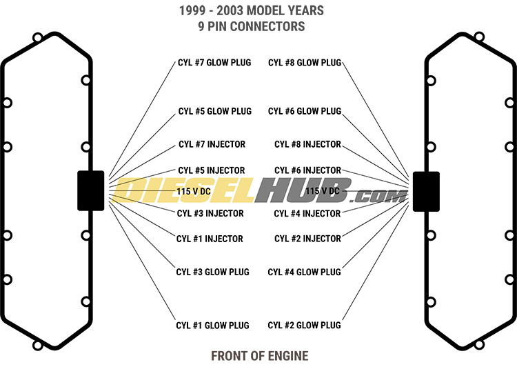
If a glow plug circuit has high resistance or no continuity between the GPCM and actual glow plug connector, disconnect the engine wiring harness at the UVCH pass-through connector and repeat the test. This technique will determine whether the flaw is in the main engine wiring harness or the UVCH. Figure 6 and 7 (below) provides pinout diagrams for the UVCH.
Test the Glow Plugs
Glow plugs are tested by measuring the resistance across the heating element. Ideally, this is accomplished by attaching one probe to the terminal and the other to the body of the glow plug (a flat of the integral nut, for example) or a nearby, good ground. Ford specifies that 0.1 to 2 Ohms (Ω) of resistance is acceptable. We prefer to see glow plugs measure between 0.8 and 1.2 Ω of resistance. Glow plugs should be replaced in full sets of (8) so that they are all the same age and the same performance and service life can be expected cylinder-to-cylinder.
Since power to each glow plug travels through the UVCH, it is possible to Ohm out each glow plug without removing the valve cover. Referring to figure 6/7 (above), measure the resistance between the appropriate pin of the valve cover gasket pass-thru connector and a good ground; if the resistance readings are within spec, the condition of both the glow plugs and under-valve cover glow plug harness are verified good. If any resistance reading is out of spec, remove the valve cover and test the individual glow plugs and UVCH to discover which is the culprit.
Under no circumstances should the engine harness side of the 5 pin or 9 pin UVCH connectors be probed with the key in the "ON", "RUN", or "CRANK" positions - one of the terminals in each connector receives high voltage (~ 115 volts DC) from the IDM and the risk of electric shock is high.
Summarized Diagnostic Procedures
The source of a glow plug system malfunction will be discovered during one of these troubleshooting subroutines:
- Verify battery condition, charge as necessary
- Read diagnostic trouble codes, decipher affected component(s) as applicable
- Verify relay coil side operation
- Verify relay switching circuit, brown wires should read battery voltage to ground during preheat sequence
- Verify condition of individual glow plugs by measuring the resistance between the terminal and a good nearby ground (or the lower body of the glow plug)
- Verify good continuity through valve cover pass-through connections


Editor, Diesel Hub