Applicable Models:
1999 - 2003 Ford F-250, F-350, F-450, F-550 Super Duty
2000 - 2003 Ford Excursion
2000 - 2003 Ford F-650, F-750
2000 - 2003 Econoline E-350, E-450, E-550
Applicable Engine(s):
7.3 liter Power Stroke V-8 (7.3 DIT)
Late 1999 and newer 7.3 Power Stroke engines with a California emissions package utilize a glow plug control module (GPCM) in lieu of the traditional relay setup found on engines with Federal emissions package. The GPCM provides more sophisticated diagnostic functions through the OBD-II system. It can, for example, identify and set DTCs for faults in individual glow plug circuits. This feature is possible because the glow plug control module has an output circuit for each individual glow plug, as opposed to the relay system in which an output is provided for each bank of cylinders.
Location and Description
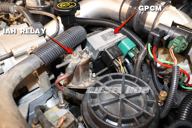
The glow plug control module is situated on a bracket that mounts using the passenger side valve cover studs. It is in the same location that a relay would be mounted on an engine with Federal emissions. The IAH relay is mounted just forward (towards radiator) of the GPCM. Two large connectors feed into the GPCM from the main engine wiring harness. The shell of the GPCM is cast aluminum and has heat sink features on the topside. The exact same component is used on both the 6.0 and 6.4 Power Stroke engines (Motorcraft part number DY1600, Ford part number YC3Z-12B533-AC).
Enhanced diagnostics are made possible because the GPCM has a single output circuit to each glow plug. This is opposed to the relay-type systems in which power at the relay is distributed to each cylinder head from a single shared output terminal. Additionally, a communication line between the GPCM and PCM permits data transfer. DTCs can therefore be activated when an open or short is detected in any individual glow plug circuit. Furthermore, the PCM will set DTCs if communication with the GPCM is lost, power to the GPCM is lost, or a short is detected in any of the related circuits. Specific, in-depth diagnostic information is available here: 7.3 Power Stroke glow plug diagnostics.
GPCM Connector Pinouts
Two large connectors attach to the GPCM, one of which is green and one that is black. The black and green connectors are not interchangeable and glow plug function will be impeded if the connectors are misplaced. Although they are physically identical, the green connector utilizes (7) terminals while the black connector only uses (6). Furthermore, the green connector is responsible for cylinders 1, 3, 5, and 7 (right or passenger side bank) and the black connector manages cylinders 2, 4, 6, 8 (left or driver side bank). A pinout diagram is provided in the figure and table below.
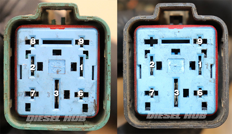
| Pin Number | Green Connector | Black Connector |
|---|---|---|
| 1 | Output to glow plug #5 | Output to glow plug #6 |
| 2 | Output to glow plug #7 | Output to glow plug #8 |
| 3 | Battery positive input (V+) | Battery positive input (V+) |
| 6 | Output to glow plug #1 | Output to glow plug #2 |
| 7 | Output to glow plug #3 | Output to glow plug #4 |
| 8 | PCM control circuit | N/A - no terminal |
| 9 | GPCM diagnostic communication output | Vehicle power relay input |

