Applicable Models:
1994.5 - 1997 Ford F-250, F-350, F-Super Duty
1999 - 2003 Ford F-250, F-350, F-450, F-550 Super Duty
2000 - 2003 Ford Excursion
1995 - 1999 Ford Econoline E-350
2000 - 2003 Ford F-650, F-750
2000 - 2003 Econoline E-350, E-450, E-550
Applicable Engine(s):
7.3 liter Power Stroke V-8 (7.3 DIT)
The high pressure oil pump (HPOP) is quite literally the heart of the 7.3 Power Stroke HEUI system. Insufficient oil pressure to the fuel injectors impedes their function. The system is designed to operate between approximately 500 and 3,000 psi of oil pressure, translating to a maximum injection pressure of roughly 21,000 psi (pressure at the injector nozzle). For additional information on HEUI injectors and the mechanics behind pressure intensification, refer to: HEUI Fuel Injectors.
A minimum 500 psi is required to permit injector operation, with most engines producing between 500 and 700 psi at idle. At full load, most engines will see peak pressure reach 2,600 to 2,800 psi. A pressure relief valve incorporated into the injector pressure regulator pops its seat once pressure reaches 3,000 psi.
The High Pressure Oil Pump
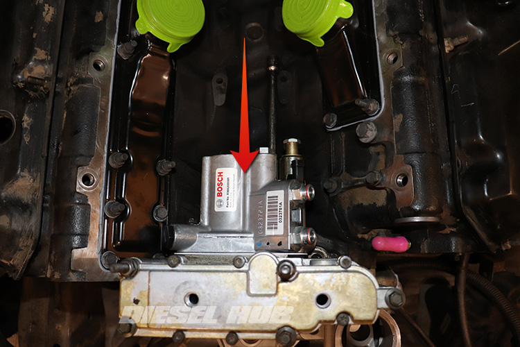
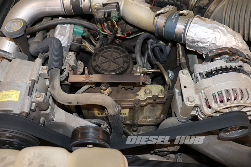
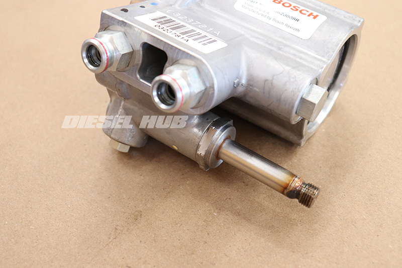
The 7.3 Power Stroke utilizes a swash plate type axial piston hydraulic pump to supply highly pressurized engine oil to the corresponding cavity in each fuel injector through a network of channels cast into the cylinder head. The pressure of the oil in this system is referred to as the injector control pressure (ICP) and it is completely separate from the low pressure oil system, which is responsible for maintaining lubrication throughout the engine.
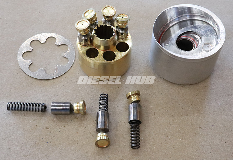
In an axial piston pump, a series of pistons rotate against a stationary swash plate. The motion is described well in the following video: swash plate pump animation. Note that the swash plate angle is fixed on the Power Stroke's high pressure oil pump. Pumps from early engines have a 15 degree swash plate angle, while late 1999 and newer engines utilize a 17 degree angle. The cylinder block is machined from a brass alloy and holds (7) pistons, which have a 0.43 inch outside diameter and 0.3 inch inside diameter.
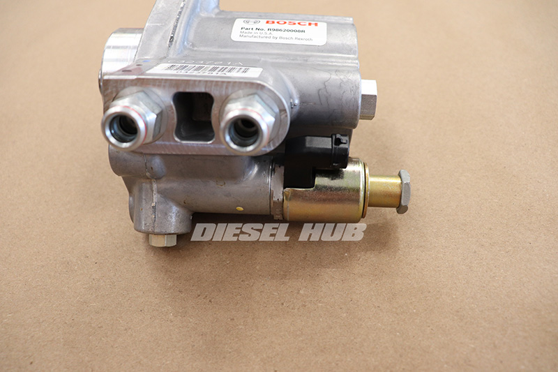
Pressure is regulated by an electronic solenoid called the injector pressure regulator (IPR) valve, which is controlled by the PCM. The IPR valve is mounted through an orifice in the body of the HPOP and bleeds off excess pressure to the crankcase, as commanded by the PCM. A pair of high pressure hoses connect each cylinder head oil rail to the outlets of the pump. Inside the cylinder heads, integral passages distribute oil to each individual fuel injector.
HPOP Differences in Early and Late Engines
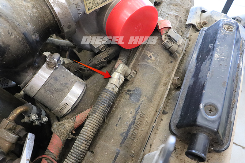
1994 to 1997 model year engines utilize flared hose fittings to connect the left and right bank high pressure oil hoses to the cylinder head and pump. Eaton snap-to-connect fittings were adopted for the 1999 model year update (early and late 1999 engines). STC fittings require a special tool to release a mechanism in the fitting that disconnects them. The tool is both inexpensive and easy to use, but STC fittings rely on an o-ring seal and are much more prone to leaking. Installing a STC hose is as simple as pushing the male end of one fitting into the female on another.
1994 to early 1999 engines used a HPOP with a 15 degree swash plate. The swash plate angle was changed to 17 degrees for the late 1999 update in order to increase the oil flowrate of the HPOP, which was required by the new fuel injector design. Increasing the swash plate angle increases the stroke of each piston and thus the volume of oil pumped with each revolution (7.2 cc on the 17 degree pump vs 6.8 cc with the old style pump). Due to the requirements of the new fuel injector design, a 15 degree HPOP is not compatible with late 1999 and newer engines.
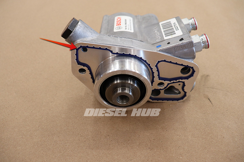
Early style pumps also had roller bearings supporting both ends of the pump shaft. However, the 17 degree pumps only have a roller bearing at the front of the shaft (closest to the drive gear) and instead utilize a fixed bushing at the rear of the shaft. The roller bearing design is obviously favorable in that it is less susceptible to wear.
Symptoms of a Faulty High Pressure Oil Pump
The first and most common symptom of a faulty high pressure oil pump is a condition in which the engine will not start when hot, but after the engine oil is allowed for cool for some period of time the engine starts without hesitation. This occurs because the engine oil becomes less viscous (thins) as the temperature increases, making it more difficult for the pump to maintain the minimum 500 psi of oil pressure at cranking speed as the result of pressure bleeding off from internal leakage.
To better explain this, consider two major factors - the thinner oil will bleed off more prominently if there is internal leakage, and the rotational speed of the pump is significantly lower while cranking than it is running (~ 180 rpm versus 650 rpm at idle). Lower than expected oil pressure in the high pressure system can also contribute to low performance, poor fuel economy, and a long crank/hard start condition.
The high pressure oil pump on a 7.3 Power Stroke is not a known weakness nor is it common for them to "grenade" in a catastrophic manner under factory operating conditions. It is significantly more likely that a HPOP will gradually wear over time, eventually showing symptoms similar to those described above. With that said, oil contamination, whether it be excessive fuel dilution or water in the engine oil, can and will cause accelerated wear within the HPOP. Low or limited oil supply to the HPOP from the low pressure system could also starve the pump and reduces its service life. Under ideal conditions, the high pressure oil pump maintains a constant supply of engine oil within the pumping chambers and is well lubricated.
HPOP Diagnostics
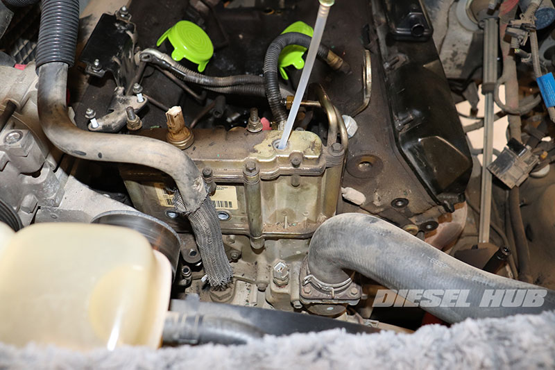
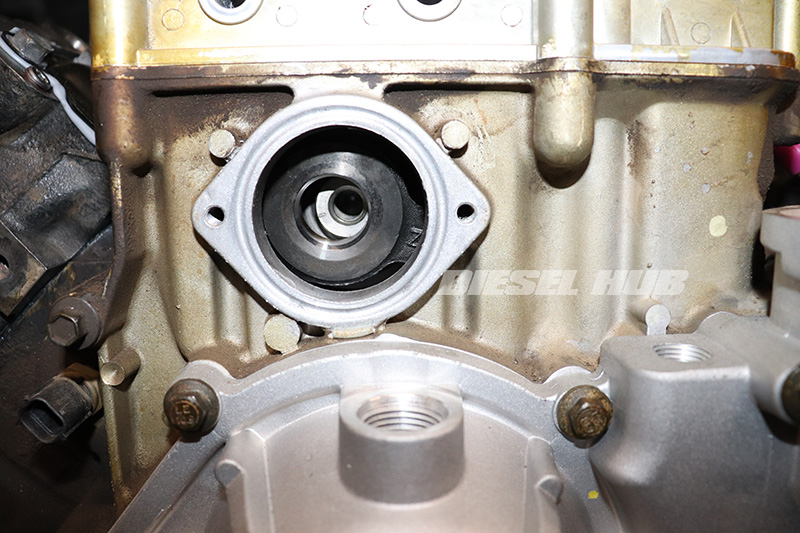
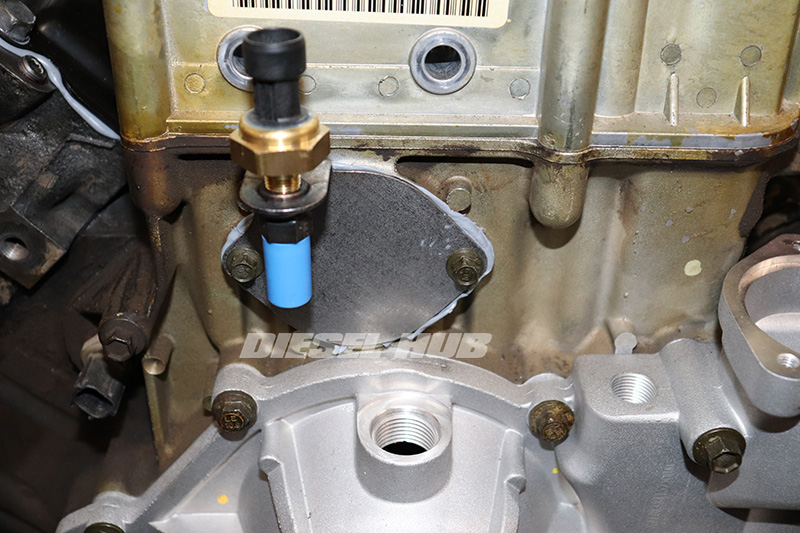
If a long crank, hard start, or no start condition is present, verify that there is oil in the HPOP reservoir. The reservoir holds approximately 3/4 to 1 quart of oil, which is used to keep the pump supplied for a brief period during engine cranking. After the engine starts the lube oil pump maintains a constant flow of oil to the reservoir, continuously feeding the pump.
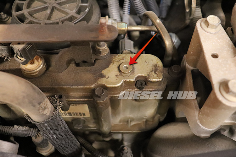
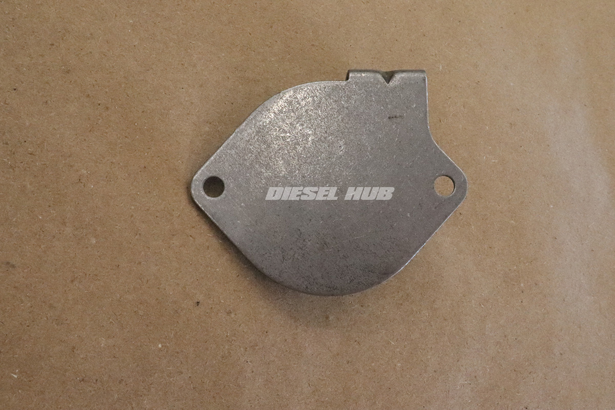
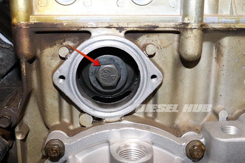
Remove the inspection plug (figure 3 below) from the top of the reservoir cover and verify that the oil level is roughly 1 inch below the top of the reservoir. A lack of oil in the reservoir is characteristic of a worn low pressure oil pump or other oil pressure concern in the low pressure system; there is insufficient flow to maintain the reservoir level or the check valve incorporated into the front cover passage is allowing oil to drain off. This will need to be corrected before any further diagnostics can be performed.
Basic high pressure oil pump diagnostics require the use of a scantool or diagnostic software with enhanced functionality that includes the ability to monitor the ICP and IPR valve duty cycle values. From this point, we also need to assume that the ICP signal is accurate and that the IPR valve is functioning correctly. A quick method for loosely verifying the ICP signal is to read the value with the engine off, preferably after it has been sitting so that the system is not holding any residual pressure. If the ICP is showing pressure when it should be zero, the sensor is faulty.
A high IPR valve duty cycle is indicative of a worn HPOP. It signifies that the IPR valve is being held closed more than usual to compensate for reduced pressure and flow. The IPR valve duty cycle is commanded by the PCM and will range between 0 and 50% depending on the operating conditions. The IPR valve is open (bleeds off pressure) at 0% and is closed (raises pressure) at 50%; the higher the duty cycle, the greater the pressure the PCM is commanding.
While cranking the engine, it is normal for the IPR valve duty cycle to exceed 30% briefly, but the engine should start fairly quickly once ICP reaches ~1,500 psi. If ICP is low and slow to climb, even with the IPR duty cycle above 30%, there is a definitive malfunction with this system. With the engine running at idle, the IPR duty cycle should remain at or below 16%. If the IPR valve duty cycle is significantly greater than 16%, the HPOP is having difficulty maintaining pressure. If the IPR valve duty cycle increases significantly after the engine oil has been brought up to operating temperature, the HPOP is again the likely culprit.
In summary, consider the following when a high pressure oil issue is suspected:
- Monitor IPR and ICP if there is a no start condition - high IPR duty cycle and low ICP is indicative of a worn pump
- High IPR valve duty cycle at idle is indicative of a worn HPOP
- ICP pressure should increase proportionately (and fairly quickly) in response to an increase in IPR valve duty cycle
- If IPR valve duty cycle remains low while cranking, suspect faulty IPR valve
- Low ICP and low IPR does not immediately point to a pump - unexpected IPR valve duty cycle is more indicative of a problem with the valve itself
- High pressure oil pumps typically last 125,000 to 150,000 miles before there is sufficient "wear" for performance to diminish
- Abrupt high pressure oil pump failures are rare, especially at stock power levels - they don't often "grenade" unless there is an oil supply issue and the pump is starved.
Part Numbers
| Component | Part Number | Remarks | |
|---|---|---|---|
| High pressure oil pump | 1994-1995 | Bosch HP004X | [1] |
| 1996-1997 | Bosch HP005X | ||
| 1999-2003 | Bosch HP008X | ||
| HPOP gasket | 1994-1995 | Ford F4TZ-9417-A | --- |
| 1996-2003 | Ford F6TZ-9417-AA | ||
| HPOP gear access cover | 1994-1997 | Obsolete | [2],[3] |
| 1999-2003 | Ford F81Z-9J432-AA | ||
| HPOP gear bolt | Ford W302170 | [4] | |
| HPOP gear washer | International 1818210C1 | ||
| HPOP hose, driver side | 1994-1997 | Ford F6TZ-9S317-A | [5] |
| 1999-2003 | Ford YC3Z-9J323-E | ||
| HPOP hose, passenger side | 1994-1997 | Ford F6TZ-9S317-A | |
| Early 1999 | Ford F81Z-9J323-E | ||
| 1999.5-2003 | Ford YC3Z-9J323-F | ||
| STC hose fittings | @ pump | Ford F81Z-9C402-AA | [6] |
| @ cylinder head | Ford F81Z-9N332-AA | ||
| Fuel filter | 1994-1997 | Motorcraft FD-4595 | [7] |
| 1999-2003 | Motorcraft FD-4596 | ||
| Fuel bowl hose kit | Dieselply DP-1637K | [8] | |
| Fuel line sleeve kit | Dieselply DP-1610K | [9] | |
| Engine oil filter | Motorcraft FL-1995-A | [10] | |
| RTV sealant | Motorcraft TA-31 | [11] | |
[1] - Bosch is the OE manufacturer. 1994 to early 1999 engines used a 15 degree HPOP, late 1999 to 2003 engines used a 17 degree pump.
[2] - Obsolete part, recommend an aftermarket billet replacement if needed
[3] - 1999 and newer engines have a gear access cover that incorporates the EBP sensor mount
[4] - Bolt and washer can be reused
[5] - 1994 to 1997 HPOP hoses are sold as a set, 1999 and newer hoses are sold individually
[6] - Replace if leaking; can be reused
[7] - Replace fuel filter after filter housing is reinstalled
[8] - Only required for 1994 to 1997 engines
[9] - Compression sleeves only required for 1999 to 2003 engines
[10] - Replace engine oil and lube oil filter after installing a new HPOP
[11] - Used to seal HPOP gear access cover; high grade, long life sealant
Preventing Engine Rotation
The high pressure oil pump is not timed to the engine and thus the gear can be reinstalled in any position. Once installed, the drive gear remains secured to the shaft by an interference fit (no keyway) and thus the drive gear bolt must be torqued down properly to prevent slipping and misalignment. More often then not, the engine begins rotating before the 95 ft-lbs torque specification is achieved. It is therefore necessary to prevent engine rotation while torquing the HPOP drive gear bolt.
There is an extremely simple solution in vehicles equipped with a manual transmission - placing the selector in a high gear (5th or 6th) and setting the parking brake provides sufficient resistance. Vehicles equipped with an automatic transmission do not have this luxury because the torque converter always allows rotation (this is why the engine can idle in any gear, including park).
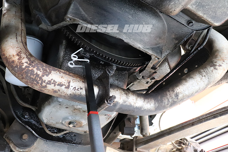
For this reason, tool 303-103 (updated tool is OTC 6891) is available to secure the flexplate and prevent rotation. Using a flywheel/flexplate turner can also accomplish the same task. If one person secures the flexplate and prevents it from turning, another can torque down the drive gear bolt. It is worth attempting to torque the bolt down without locking the flexplate first.
How to Replace the HPOP on a 7.3 Power Stroke Engine
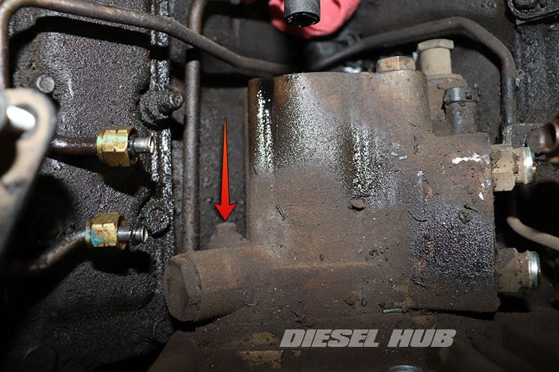
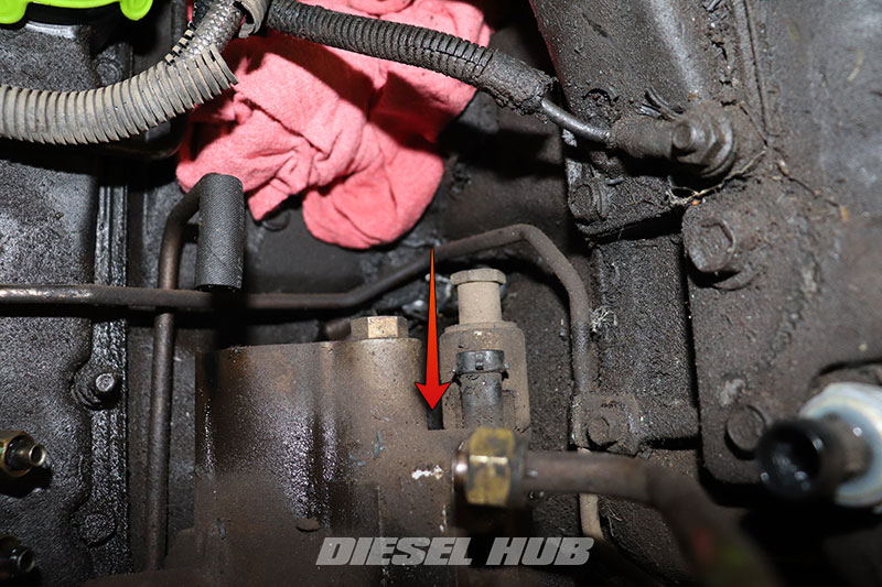
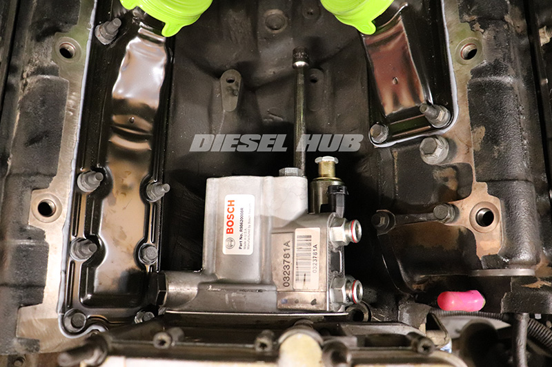
The procedures are largely similar for all 7.3 liter Power Strokes, however there are some subtle differences in early and late model engines. Procedures that are limited to only early or only late style engines are identified in the instructions below. For these purposes, an early engine is considered one that has the exhaust backpressure sensor located at the rear, passenger side of the HPOP reservoir. A late engine will be considered one with the exhaust backpressure sensor mounted to the HPOP gear access cover in front of the reservoir.
Click any thumbnail to view fullsize, detailed image
- Disconnect both negative battery cables.
- If applicable, remove the plastic "Power Stroke" engine cover and mounting bracket.
- Remove the accessory drive (serpentine) belt.
- Locate the radiator drain valve on the driver side, lower corner of the radiator.
- Optional - attach a 1/2 inch hose to the radiator drain valve to reduce splashing and spillage.
- Drain the radiator into suitable containers. Good engine coolant drained into clean containers can be reused.
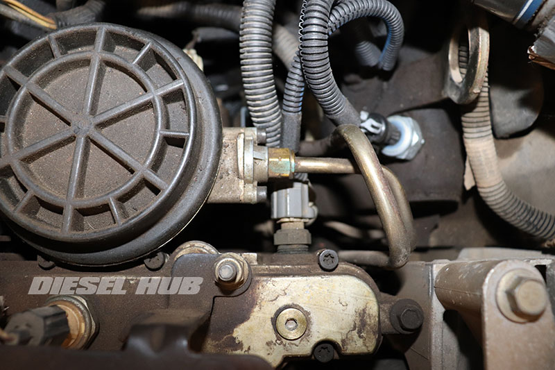
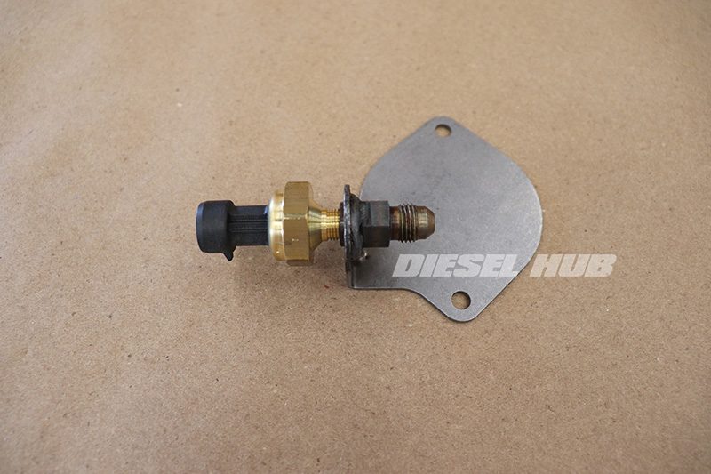
- Disconnect the exhaust backpressure (EBP) sensor connector and remove the EBP tube at the bracket fitting with a 5/8 inch flare-nut wrench.
- Remove the (2) nuts that secure the EBP sensor bracket to the HPOP reservoir with a 13 mm socket.
- Remove the EBP sensor bracket assembly from the reservoir and set aside.
- Disconnect the exhaust backpressure (EBP) sensor connector and position it out of the way of the high pressure oil pump (HPOP) access cover.
- Disconnect the EBP sensor tube at the EBP sensor bracket; see 7.3 Power Stroke EBP sensor removal for additional guidance. In order to position the tube out of the way, you may want to loosen it at the exhaust manifold, or remove it entirely.
- Remove the heater hose positioned adjacent to the HPOP gear bolt access cover that connects to the fitting threaded into the top of the water pump housing.
- Remove the water pump fitting with a 1 inch wrench. It is possible to work around it, but provides convenient access to the inside of the HPOP drive gear access cover with it removed.
- Completely drain the fuel filter housing (yellow fuel drain valve switch).
- Disconnect the IPR valve connector (IPR valve protrudes from the driver side, lower corner of the HPOP).
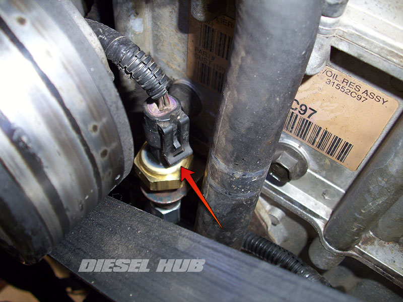
- Disconnect the ICP sensor connector (front, driver side cylinder head).
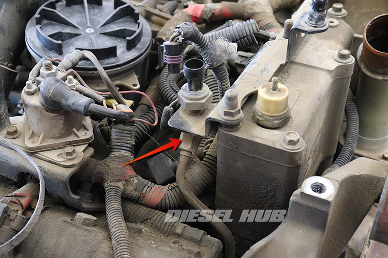
- Disconnect the oil temperature sensor at the rear of the HPOP reservoir (towards driver side).
- Disconnect the oil pressure sensor at the top of the HPOP reservoir (towards passenger side).
- Remove the fuel filter housing from the engine. For specific details, refer to: OBS fuel bowl removal or Super Duty fuel bowl removal.
- Remove the HPOP reservoir inspection plug with a 3/16 inch hex (Allen) driver or key (top, driver side of HPOP reservoir).
- Using a fluid extraction tool, extract all engine oil from the HPOP reservoir. Between 3/4 and 1 quart of engine oil should be stored in the reservoir.
- Place several shop rags in the engine valley below and around the HPOP to collect any residual oil when the pump and hoses are disconnected.
- Loosen the high pressure oil pump hoses on both cylinder heads with an 11/16 inch wrench.
- Trace the hoses and loosen them at the HPOP outlet ports.
- One at a time, completely loosen each hose and remove it from the engine compartment (the hoses will be full of oil). If the pump is being replaced, new hoses should be used.
- Disconnect the high pressure oil pump hoses at each cylinder head and the HPOP outlet ports.
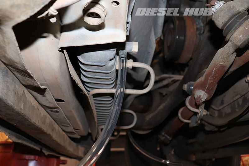
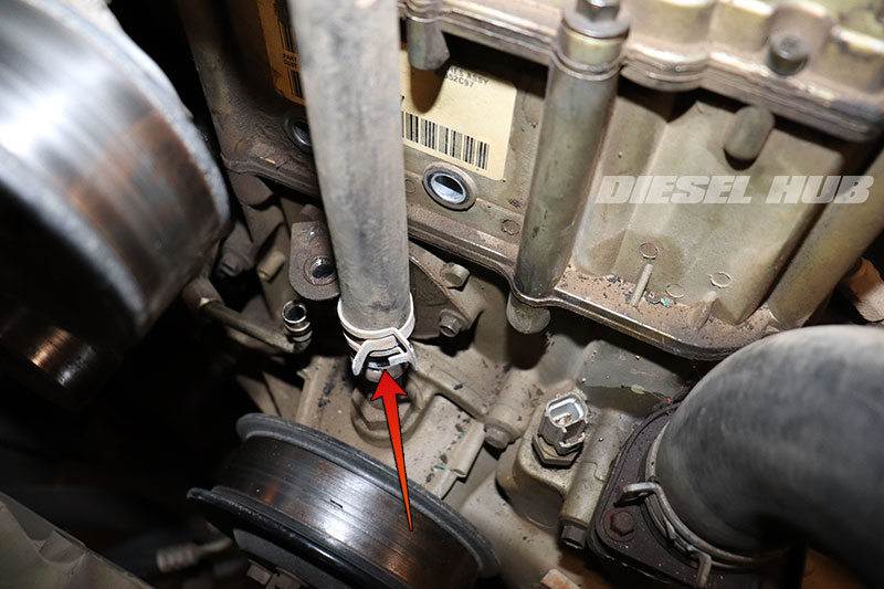
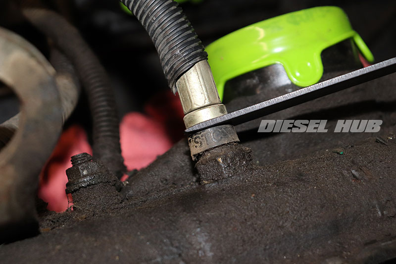
- The STC (snap to connect) fittings are released by wedging a STC fitting tool (recommend OTC 6594) between the rubber bushing and metal hose fitting (as pictured). This action relieves the internal lock ring so that the male and female halves of the fitting can be separated.
- Consider replacing the STC fittings if they appear to be weeping oil.
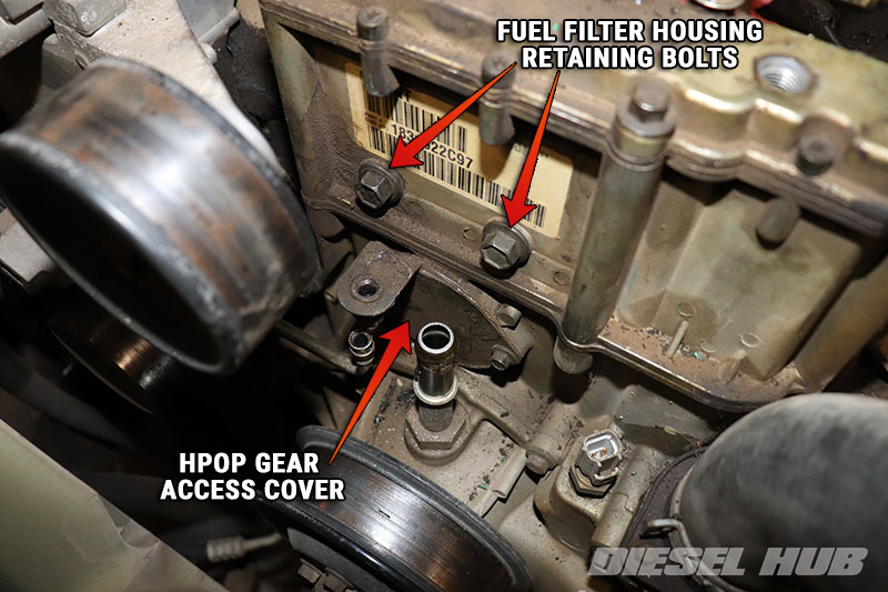
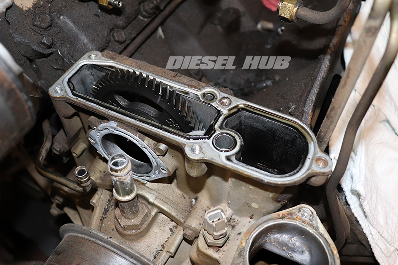
- Remove the HPOP gear access cover (integral EBP sensor bracket on late engines) bolts with an 8 mm socket.
- Remove the HPOP gear access cover; carefully pry the edges with a flat blade screwdriver or thin profile pry bar to release the silicon seal.
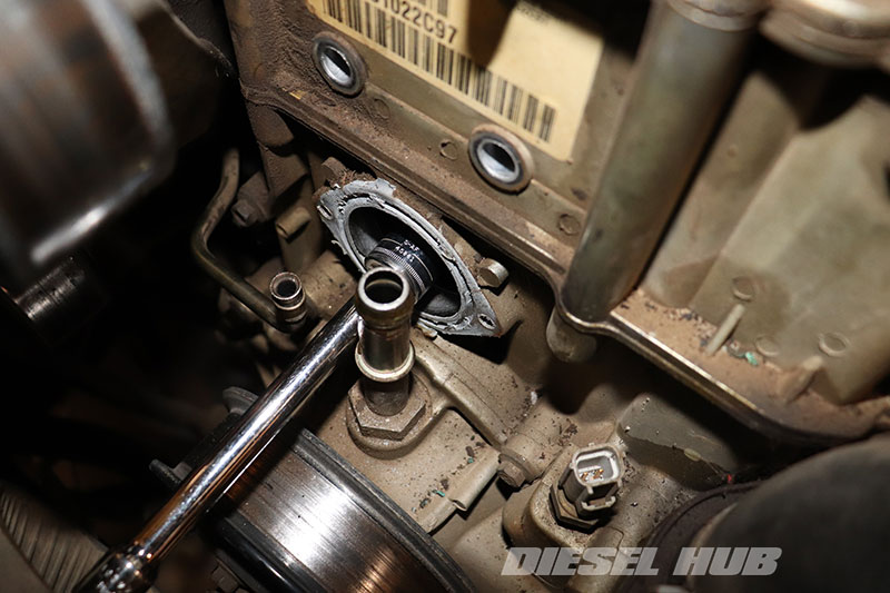
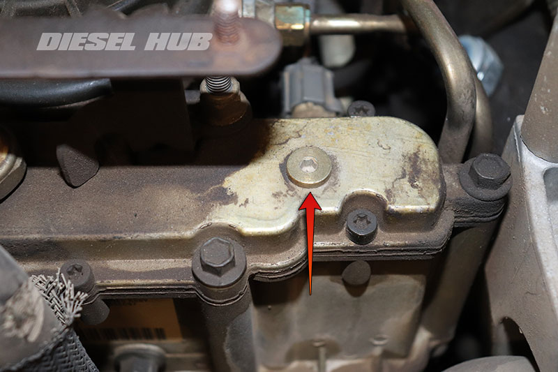
- Loosen the HPOP drive gear bolt using an 18 mm socket. If the water pump nipple was left in place, a shallow socket will be necessary as the nipple will interfere with a deep socket.
- Carefully remove the drive gear bolt and washer; do not drop the washer into the front cover.
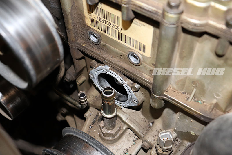
- Remove the (2) HPOP mounting bolts with a 10 mm socket.
- Note that the driver side bolt is hidden from view and is located towards the passenger side of the IPR valve; feel around to find the head.
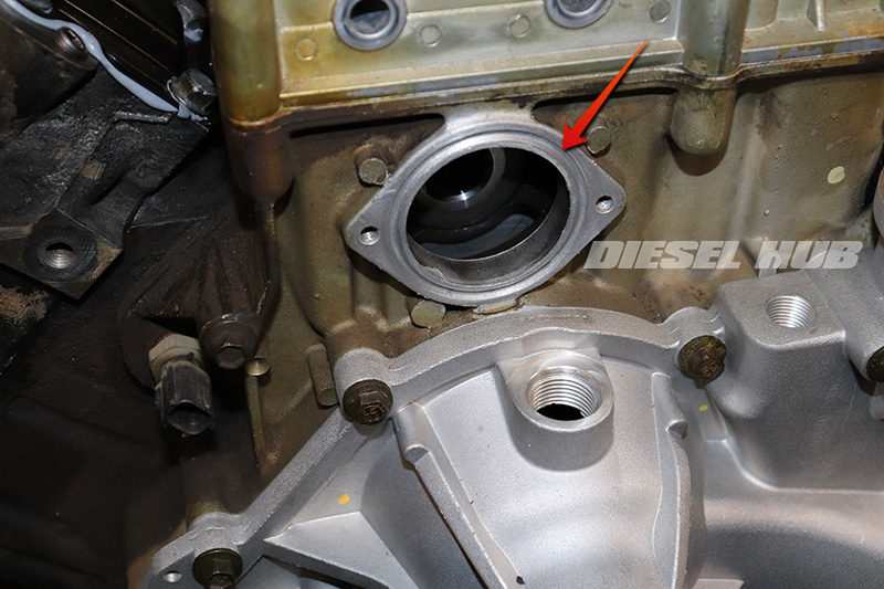
- Once the retaining bolts have been removed, pull the pump away from the reservoir and maneuver it out of the engine compartment.
- The pump retains a significant amount of oil, so be prepared to catch spills with a shop rag.
- It is highly recommended, but not required, that the high pressure oil pump reservoir is disassembled and resealed at this time. It is a fairly simple process requiring two additional gaskets on late engines a single gasket on early engines. See 7.3 Power Stroke HPOP reservoir reseal for additional information on this process.
High Pressure Oil Pump Installation
- Clean up any oil accumulated in the engine valley once oil stops spilling out of the reservoir opening.
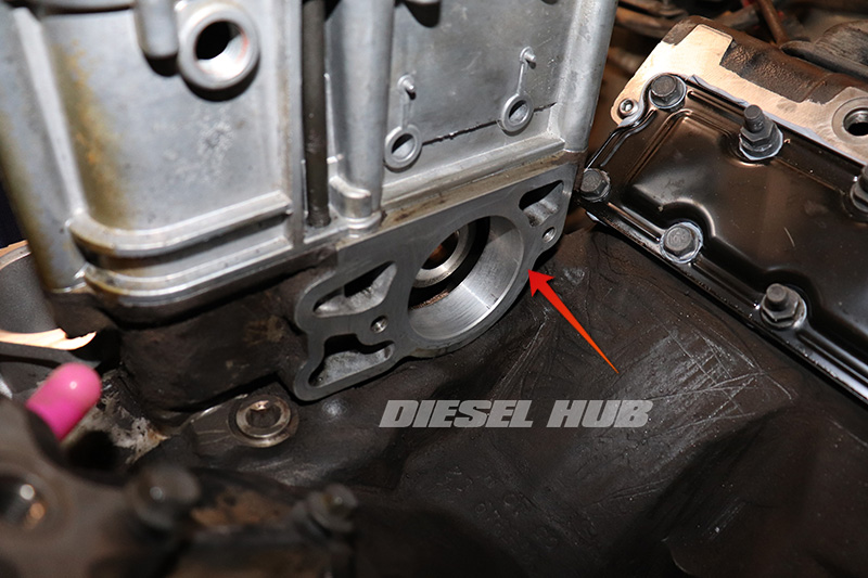
- Clean and prep the HPOP gasket mounting flange on the backside of the reservoir. It should be free of debris and gasket remnants before proceeding. Use a clean shop rag to prevent foreign contaminants from entering the reservoir.
- Thoroughly clean and prep the HPOP gear access cover mounting area. It should be free of debris, sealant remnants, and oil residue before proceeding. Use a clean shop rag to prevent foreign contaminants from entering the reservoir.
- Thoroughly clean the HPOP gear access cover. The cover must be free of debris, sealant remnants, and oil residue.
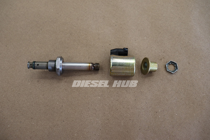
- If the IPRV valve is bring reused, disassembly and remove it from the old HPOP. The correct order and position of components is depicted in the image at left. The o-rings on the nose of the valve should be replaced before installing it into the new pump.
- Thread the body of the IPR valve into the HPOP with an IPR valve socket (extra deep 1-1/8 socket). Torque the body to 35 ft-lbs.
- Assemble the remainder of the IPR valve components, noting that the orientation of the connector needs to point upright for easy access. Torque the rear jam nut to 55 in-lbs.
- Orient and install the new gasket onto the face of the high pressure oil pump.
- Maneuver the HPOP into place, then insert it into the reservoir.
- Line up the bolt holes and install the retaining bolts finger tight (use a 10 mm socket and extension, as shown, but no ratchet).
- Snug the retaining bolts in an alternating fashion, then torque to 18 ft-lbs.
- Install the driver and passenger side oil lines.
- Line up the gear onto the HPOP shaft and make sure it is positioned in place properly. Do not rely on the bolt/washer to align the gear. The gear must be properly aligned onto the shaft by hand before installing the bolt (misaligned gear depicted in image at left).
- Install the HPOP gear bolt and washer, then torque the bolt to 95 ft-lbs.
- If engine is rotating and preventing the bolt from being torqued to spec, see "Preventing Engine Rotation" above.
- On late engines, it is recommended that the EBP sensor is installed before installing the access cover; it is easier to prevent bending the cover and interfering with the silicon seal if it is done at this stage instead of after the cover is installed.
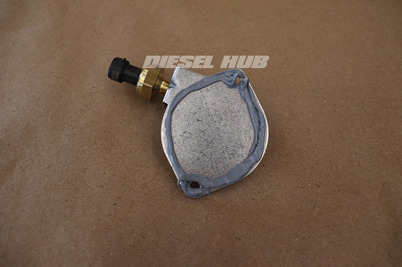
- Apply a small bead of RTV sealant to the back of the access cover - recommend Motorcraft TA-31.
- Line up the access cover to the flange, then install the bolts finger tight.
- Snug the bolts in an alternating fashion to provide an even load on the sealing surfaces, then torque to 120 in-lbs.
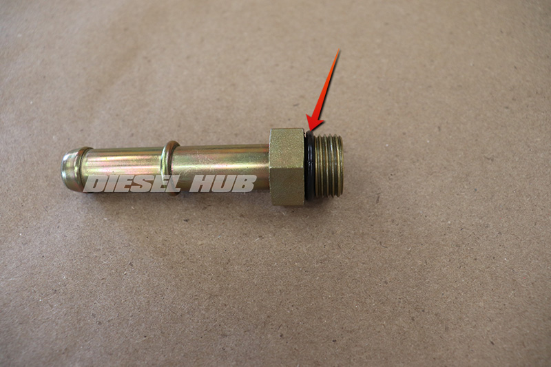
- Install a new water pump fitting o-ring (dash 116, 3/32 inch thickness).
- Reinstall the water pump fitting - do not overtighten - and heater hose.
- Reinstall the fuel bowl and other components in reverse order. Early model fuel bowls should be installed with new hoses, late model fuel bowls should installed with new sleeves.
- Replenish the cooling system.
- Change the engine oil and lube oil filter.
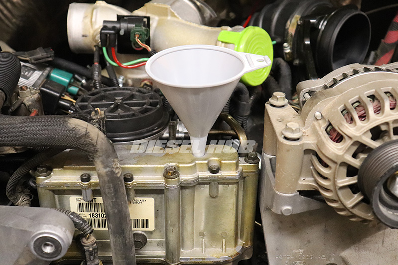
- Prefill the HPOP reservoir with clean motor oil until the level is approximately 1 inch from the top of the reservoir.
- Reinstall the access plug at the top of the reservoir snug (o-ring seal, do not overtighten).
- Prime the oil and fuel systems with the injectors disabled.
- Verify and top of engine oil level after a brief run-in period.

