Applicable Models:
1994.5 - 1997 Ford F-250, F-350, F-Super Duty
1995 - 1997 Ford Econoline E-350
Applicable Engine(s):
7.3 liter Power Stroke V-8 (7.3 DIT)
"Fuel bowl" refers to the fuel filter housing, which is responsible for more than just fuel filtration - pressure regulation and water separation also occur in the fuel bowl. Additionally, it incorporates fuel restriction and water-in-fuel sensors. A fuel heater is also located in the fuel bowl, which is designed to prevent fuel from gelling in cold conditions and a drain valve is mounted at the front of the housing to allow water to be drained off or the entire apparatus to be drained prior to service.
The fuel bowl is centrally located in the engine valley between the high pressure oil pump and turbocharger. The vast majority of the its components (internal and external) are sealed with o-rings, which have a finite life and leaks will eventually develop. Fortunately, the entire assembly is serviceable and can be rebuilt with new seals. In fact, rebuilding a filter housing is hundreds of dollars cheaper than replacing it. If the aluminum housing is not cracked, there is nothing inherently wrong with it and it can be brought back to life with an economical rebuild kit.

Fuel Bowl Parts
| Description | Part Number(s) | Remarks | |
|---|---|---|---|
| O-ring kit | 1994.5 - 1995 | DP-1640K | [1] |
| 1996 - 1997 | DP-1641K | ||
| Fuel bowl hose kit | DP-1637K | [2] | |
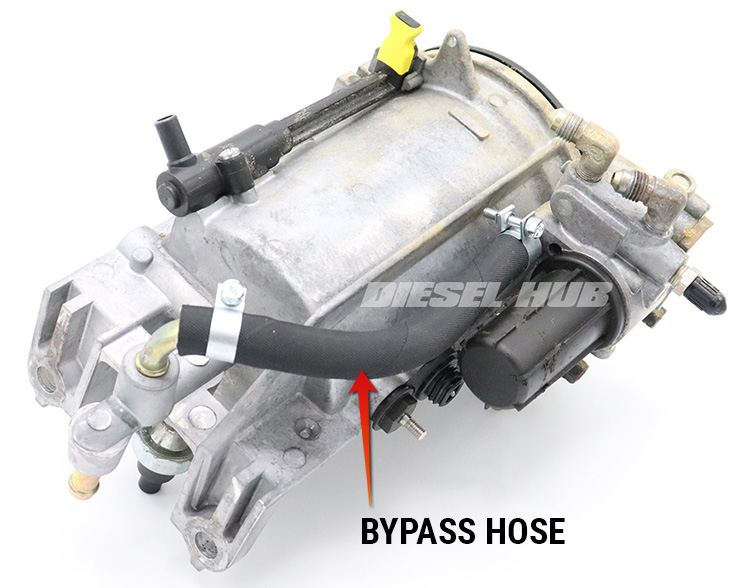
| Bypass hose | DP-163601 | [3] | |
| Fuel filter | Motorcraft FD-4595 | [4] | |
| Filter cap | Ford F5TZ-9G270-A | [5] | |
| Updated test fitting/bleed port | DP-160401 | [6] | |
| Bleed bushing & screen | Ford 2C3Z-9157-AA | [5] | |
| Return lines | Ford F4TZ-9D308-A (driver) | [5] | |
| Ford F4TZ-9B273-A (passenger) | |||
| Return filter & cap | Ford F5TZ-9150-A | [5],[7] | |
Pressure valve/spring kit |
Federal emissions | Ford F5TZ-9K061-A | [5],[7] |
| California emissions | Ford F6TZ-9K061-AA | ||
| Standpipe | Ford F5TZ-9236-A | [5] | |
| Drain valve | Ford F5TZ-9A153-A | [5] | |
| Fuel heater | Ford F5TZ-9J294-A | [5] | |
| Fuel heater thermostat | Ford F4TZ-9J294-A | [5] | |
| Water-in-fuel sensor | Ford F4TZ-9S281-B | [5] | |
| Fuel restriction sensor | Ford E8TZ-9S283-A | [5] | |
| Wiring harness | Ford F7TZ-9S277-AA | [5] | |
| Fuel filter housing assembly | 1994.5 - 1995 | Motorcraft FG-1052 | [8] |
| 1996 - 1997 | Motorcraft FG-1054 | ||
[1] - Early style housing found on 1994 and 1995 model year engines, late style found on 1996 and 1997 model engines; flexible bypass hose indicates early style, rigid (metal) bypass line indicates late style housing; refer to figures 1 and 2 above
[2] - Includes all hoses necessary to reinstall the filter housing to the engine
[3] - 1994 and 1995 model year engines only
[4] - Replacement required
[5] - Reusable part, replace as necessary
[6] - Converts fuel bleed/pressure test port to common 1/4 inch flare
[7] - Obsolete part, OEM replacement not readily available. Aftermarket strainer 160204 available.
[8] - Filter housings that are cracked are not salvageable, replacement required; includes new harness and filter
Proper O-ring Installation
While there are some rare occasions where o-rings are installed dry, they are typically generously coated in clean engine oil before installed on engine and fuel system components. This performs several functions, including:
- Ensures smooth installation with minimized binding action that could tear or damage o-ring
- Minimizes residual stresses in the installed o-ring by limiting twisting and binding, allowing the o-ring to rest in a more "natural" orientation
- Provides lubrication between the o-ring and sealing surfaces
O-rings that are installed dry are more likely to bind, twist, and become pinched. Applying motor oil before installation is the best way to safeguard the integrity of the seal.
Cleaning Tips & Techniques
Most of the "hard" components in the fuel bowl assembly are entirely reusable so long as they are not damaged, but everything must be cleaned well before reassembly. Contaminants that find there way into any of the various passages could ultimately end up in the "filtered" fuel circuit without actually passing through the filter, subsequently traveling through the fuel pump and into the gallery in the cylinder heads that feed each injector.
Plastic components are best cleaned with warm water and light brushing. Avoid harsh solvents (brake cleaner, carb and choke cleaner, acetone, mineral spirits, etc) as they will chemically react and break-down these materials. Plastic safe electrical connector cleaners (ex: CRC electronic cleaner) are safe for such parts in small doses and can be used to help break up deposits on the more sensitive materials.
The primary filter housing and pressure regulator housings are cast aluminum, which will withstand heavy solvents. These components should be entirely degreased and each passage, cavity, and orifice should be blasted out with an aerosol cleaner before final assembly. Compressed air can also be used to clear out these passages so long as it is filtered. Water-based degreasers are generally safe to use with aluminum components, but there are exceptions - verify the manufacturers recommendations before use. For heavily soiled components, an overnight soak in diesel fuel will help kick-start the degreasing process.
Disassembly & Assembly Procedures
Click any thumbnail to view fullsize, detailed image

- Refer to 7.3 Power Stroke fuel bowl removal if filter housing has not yet been removed.
- Remove the single screw holding the wiring harness connector to the side of the filter housing.
- Fish the wiring harness wires through the opening in the bottom of the filter housing one-at-a-time.
- Remove the cap and fuel filter, then completely drain the fuel bowl.
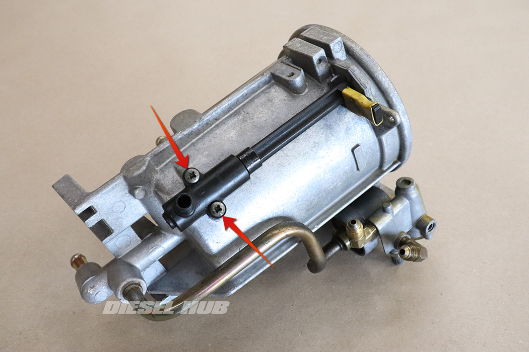
- Remove the (2) screws securing the drain valve to the filter housing with a Phillips head driver.
- Separate the drain valve from the housing; the top of the handle will slide out of the hole that it pivots in.
- Remove and discard the (2) thick o-rings that seal the drain valve to the housing.

- Remove the orifice and check ball from the upper drain valve opening. Not all filter housings contain this part, so don't be concerned if there is not one.

- Loosen the standpipe with a 7/8 inch or 22 mm crowfoot wrench. Note that the standpipe is reverse thread so you must rotate it clockwise to loosen.
- Completely unthread and remove the standpipe by hand.
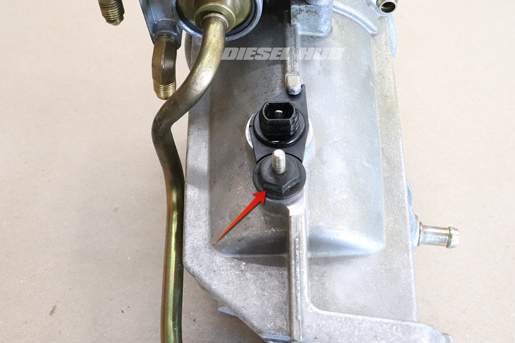
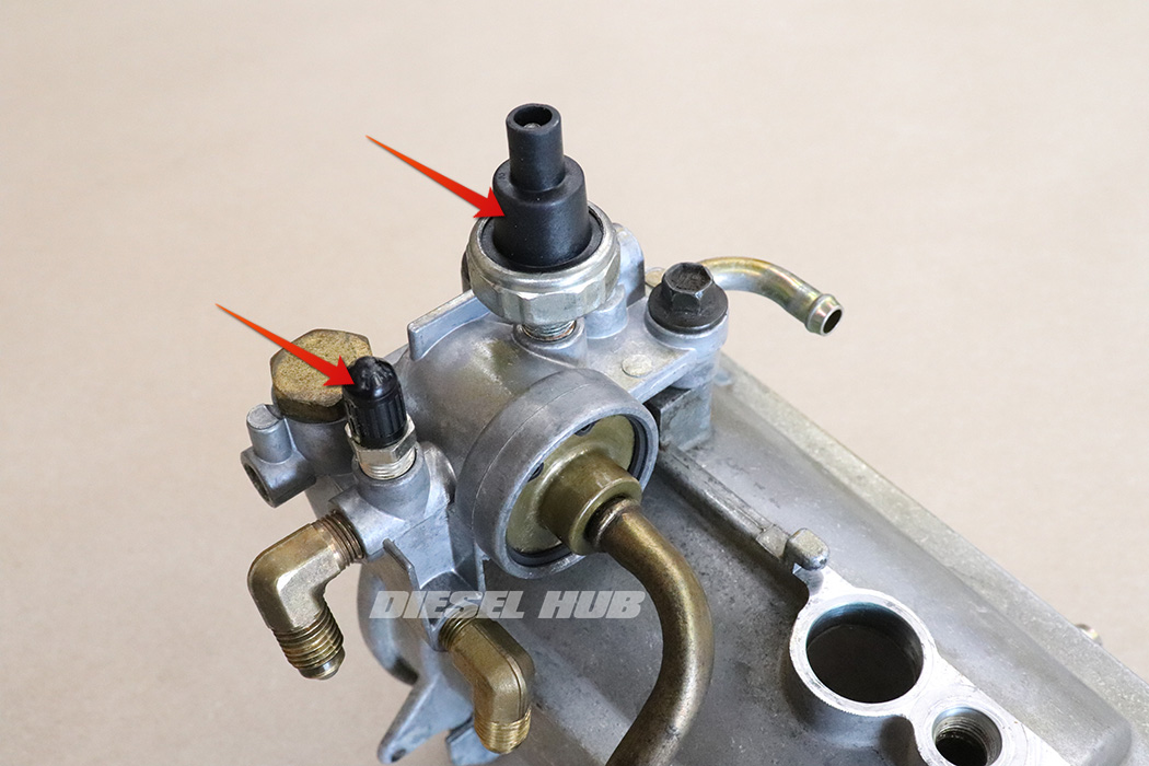
- Remove the water-in-fuel sensor with a a 9/16 inch socket or wrench.
- Remove the single o-ring from the water-in-fuel sensor.

- Rotate the fuel heater thermostat so that the edge is no longer wedged beneath the locking detent cast into the housing.
- Rotate, pull, and/or pry the thermostat to remove it from the housing. It is not threaded into the housing so the only thing securing it is the o-ring. As the o-ring ages and becomes brittle, it becomes more difficult to remove this part.
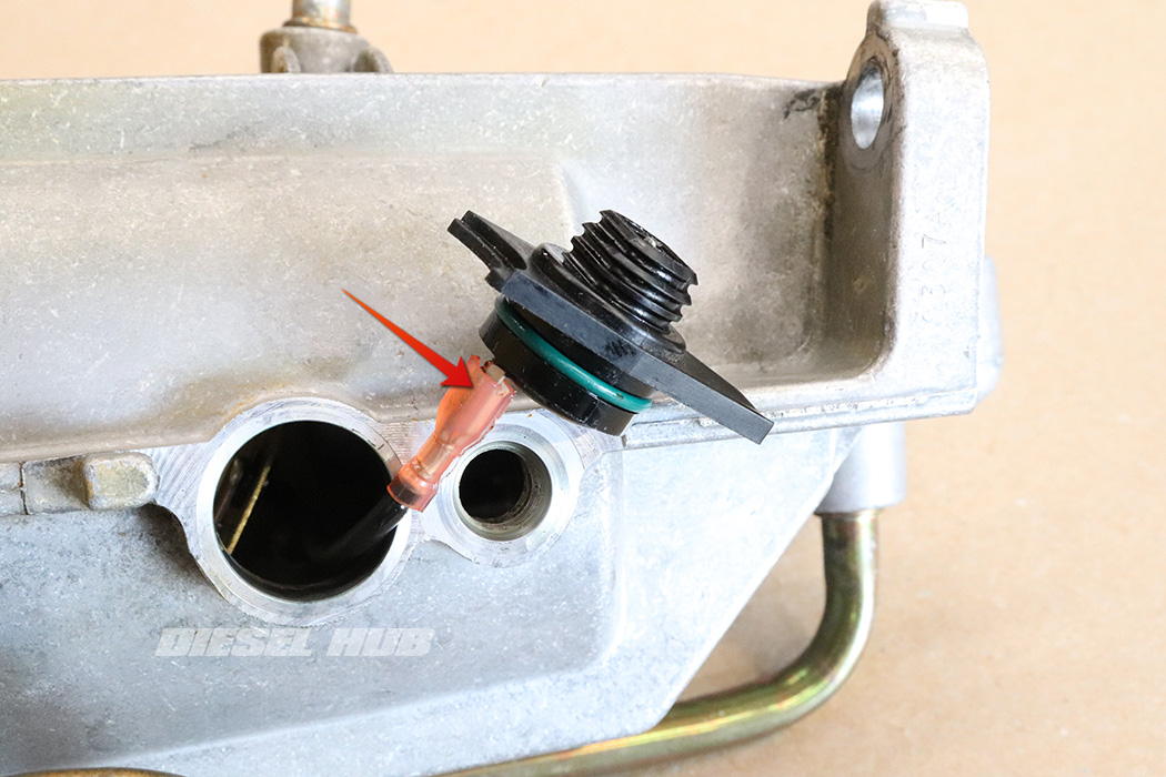
- Pull the thermostat out far enough to disconnect the fuel heater.
- Remove the fuel heater element from inside of the filter housing.
- Remove the single o-ring from the thermostat.
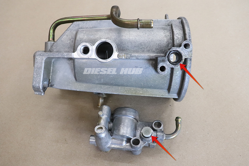
- Remove the fuel restriction sensor with a 1-1/16 inch socket. Note that on early style housings this is located at the base of the housing near the outlet fitting to the fuel pump. On later style housings it is threaded into the fuel pressure regulator assembly.
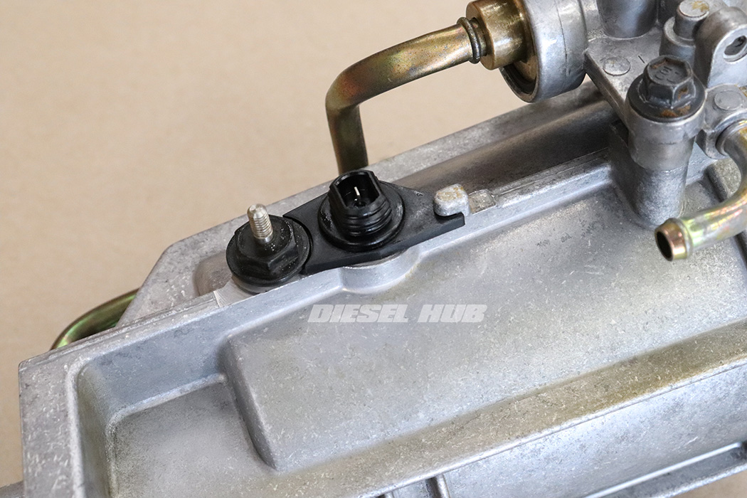
- Remove the air bleed/pressure test fitting with a 7/16 inch socket.
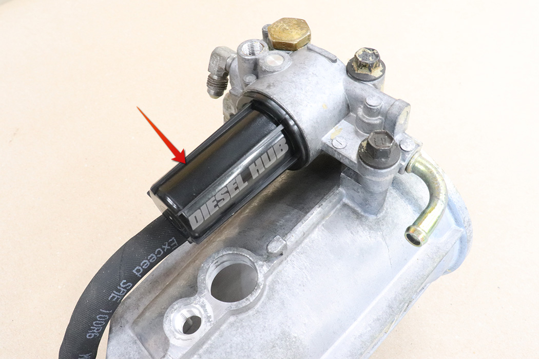
- Remove the black return filter cap. This part is obsolete and no longer available from Ford, so take care not to damage it.
- Remove the filter and spring from the cap. This filter can be blown off and reused if it is in good condition.
- Remove the single o-ring that seals the cap to the housing.

- Remove the bypass hose. If it is stubborn, cutting it in the center and/or slicing it lengthwise near the fittings can be useful.

- Remove the snap ring at the base of the pressure regulator housing where the bypass line connects.

- Remove the (2) pressure regulator housing retaining bolts with a 10 mm socket.
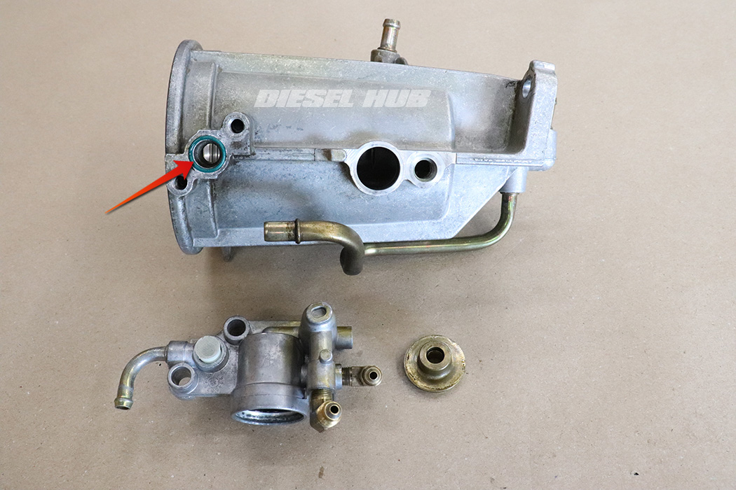
- Separate the pressure regulator housing from the fuel bowl. On late style housings, this will require pulling away from the metal bypass line. On early style housings, it should pull off the fuel bowl fairly easily. Note that there is a screen and nylon bushing in the passage between the regulator and filter housing.
- Remove the single o-ring that seals the pressure regulator housing to the filter housing.
- Remove the nylon bushing, screen, and check ball. The screen often detaches from the bushing or may even remain inside the filter housing when the pressure regulator housing is separated. The screen can be cleaned and reused, even if it separates from the bushing.
- If the nylon bushing or check ball is severely damaged, it must be replaced.
- Remove the (2) o-rings from the nylon bushing.

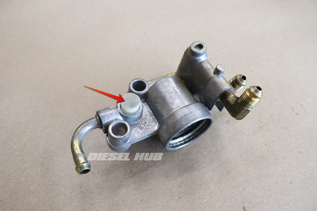
- Remove the stainless steel mesh filter from the inside of the pressure regulator housing.
- Remove the small black plastic bushing from the inside of the pressure regulator housing. A small pick can be used to grab the edge of the bushing and pull it out.

- Remove the pressure regulator spring and plunger cap (brass cap) with a 3/4 inch socket or wrench.

- Pull the pressure regulator spring and plunger out of the housing; make a note of its orientation.
- Remove the single o-ring that seals the brass cap to the housing.

- As an optional step, the return line fittings (elbows) can be removed. If they are removed, it is recommended that they are reinstalled after the filter housing is reassembled and installed in the engine valley so that the orientation of the fittings is adjusted to match the angles of the return lines.
- Note that it is very easy to overtighten these fittings and crack the housing, which will require replacement of the entire fuel bowl as an assembly.
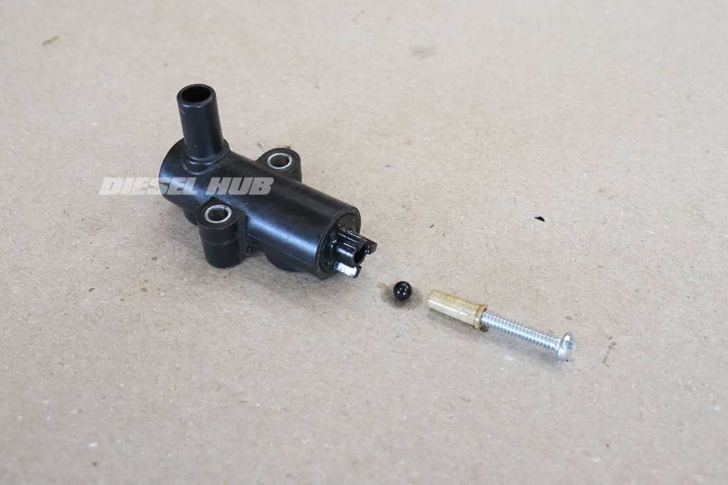
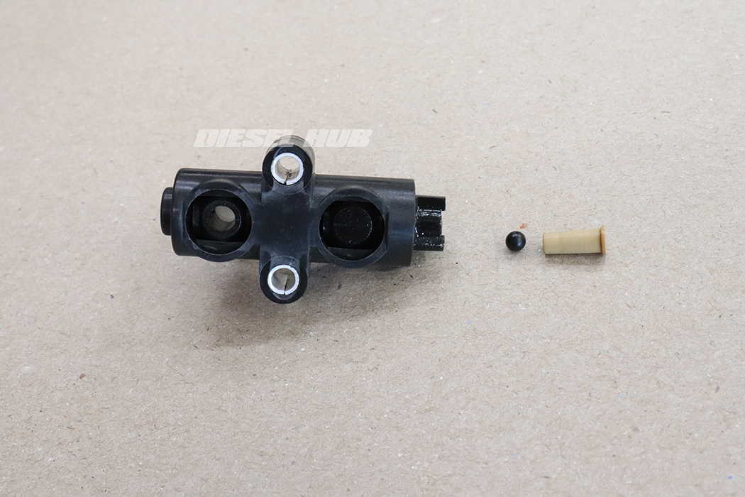
- Thread a #6 machine screw into the off-white bushing at the top of the drain valve.
- Pull the bushing out of the drain valve, followed by the small plastic ball.
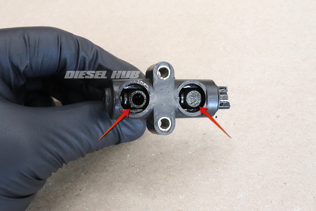
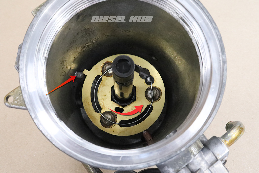
- Turn the drain handle so that the flat spots on the spheres integral to the valve stem are aligned at the rear of the valve (as pictured).
- If the flat sections are not aligned as pictured, the valve stem cannot be removed.
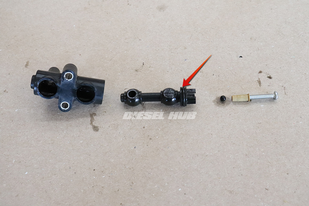
- Pull the drain valve stem out of the body (flat spots must be aligned with the openings at the rear of the valve body).
- A small screwdriver can be used to pry the stem out of the body if necessary.
- Remove the single o-ring from the drain valve stem.

- Remove the inner and outer o-rings from the brass adapter that connects the rigid bypass line to the pressure regulator housing.
- Thoroughly clean all components based on the guidance outlined in the section above.
- Thoroughly coat all new o-rings in clean engine oil prior installing them.
- Install new o-rings on the return filter cap (early only), water-in-fuel sensor, fuel heater thermostat, brass cap, nylon bushing, and drain valve stem.
- Reassembly the drain valve by inserting the stem into the body. Note that the stem must be oriented so that the flat side is facing upwards in the same plane as the rear of the drain valve (just as in removal).
- If applicable, do not forget to reinstall the plastic ball and bushing.

- Install the inner and outer o-rings onto the brass bypass line adapter.
- The inner o-ring can be tricky to install, but a pick or small screwdriver can be used to maneuver it into place. If the o-ring is not installed into the groove correctly, it will not seal.

- Reinstall the mesh screen and small plastic orifice into the bottom of the pressure regulator housing.

- Install the brass adapter plate. A bench-top arbor press works well, but a vise or c-clamp can also be used. The plate must seat evenly or it will pinch the o-ring.
- Secure the adapter plate by installing the snap ring.

- Install the pressure regulator plunger and spring.
- Note that the plunger installs first and is oriented so that the spring slides into the hole incorporated into it.
- Reinstall the brass cap, making sure that the pointed tip at its center aligns inside the pressure spring.

- Install the bypass hose and clamps, but do not secure the clamps yet.
- Install the o-ring that seals the regulator to the filter housing.
- Install the check ball, followed by the nylon bushing and screen. If the screen has separated, install it into the filter housing opening.
- Install the o-ring that seals the regulator to the filter housing.
- Install the check ball, followed by the nylon bushing and screen. If the screen has separated, install it into the filter housing opening.

- Install the pressure regulator to the filter housing.
- Take care not to pinch the o-rings or bind the nylon bushing.
- On late style housings, the regulator must be simultaneously aligned with the metal bypass line and the filter housing.
- Secure the pressure regulator to the filter housing with the (2) bolts.

- Place the fuel heater into the filter housing and orient the connector through the thermostat opening.

- Connect the fuel heater to the thermostat.
- Push the thermostat through the opening to seat the o-ring.
- Once the thermostat is fully seated, rotate it until it locks beneath the aluminum detent.
- Install the water-in-fuel sensor.
- Install the standpipe. Recall that it is reverse thread, thus it must be rotated counter-clockwise to tighten.
- Note the orientation of the tab on the fuel heater and the corresponding stop cast into the filter housing - the tab on the heater must rest against this stop such that as the standpipe is tightened, the heater element will be prevented from rotating.
- Snug the standpipe down by hand, there is no reason to risk overtightening with a wrench.

- Reinstall the small orifice and check ball into the upper drain valve opening.

- Install the handle to the drain valve. Note that the handle will only align with the stem of the drain valve one way, thus it can only be installed in the correct position.
- Install the (2) drain valve o-rings.

- Install the drain valve and start the retaining bolts.
- Verify that the o-rings are not pinched between the drain valve and housing, then finish tightening down the retaining bolts.

- The threads on the fuel restriction sensor, bleed valve, and return fittings (elbows) are tapered; do not overtighten. Overtightening any of these fittings will crack the brittle cast aluminum housing. Recommend using Loctite 545 sealant on these threads.
- Install the fuel restriction sensor and bleed valve/pressure test fitting.
- Reattach the wiring harness to the filter housing.
- If removed, reinstall the return line fittings (elbows). This is easier to do after the filter housing is reinstalled.

