Applicable Models:
1994.5 - 1997 Ford F-250, F-350, F-Super Duty
1995 - 1997 Ford Econoline E-350
Applicable Engine(s):
7.3 liter Power Stroke V-8 (7.3 DIT)
The fuel filter housing on a 7.3 Power Stroke diesel engine, often referred to as the fuel bowl, is where fuel filtration, water separation, and pressure management occurs. Additionally, there is a heating element located in the bottom of the fuel bowl to provide an added layer of protection against fuel gelling in cold weather. Once fuel is drawn in from the tank and pumped through the filter is it is distributed to passages in both cylinder heads that ultimately supplies the fuel injectors.
The filter housing on 1994 to 1997 model year engines is quite different that that found on 1999 through 2003 models. The early design is physically larger, more complex, and mounts in the engine valley. It is designed to function with the two stage mechanical (camshaft driven) fuel pump utilized in these engines. With the exception of the return lines, which use threaded flare fittings, the connections between the fuel pump, filter housing, and fuel tank are made with low pressure hydraulic hose. These textile braided hoses are quite tough and more resilient than standard fuel line so it is important that the correct hoses are used when installing a fuel bowl.
Fuel System Flow & Operation
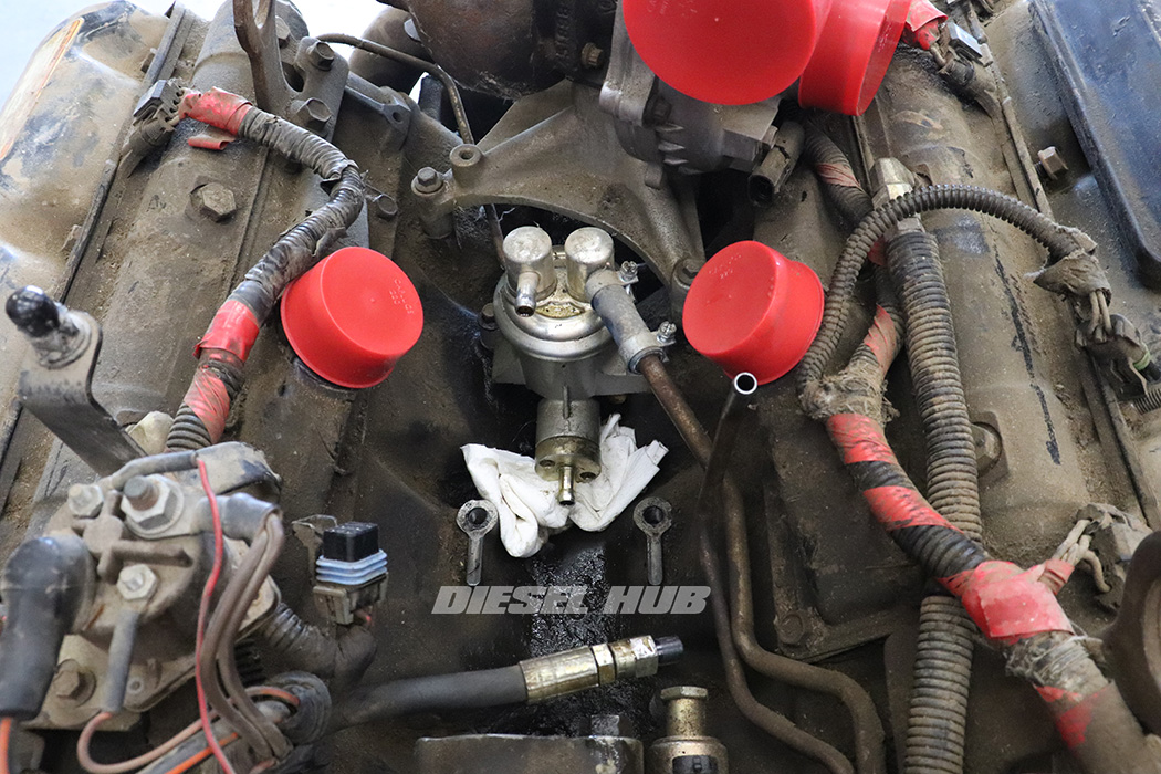
The 7.3 Power Stroke utilizes a two stage mechanical fuel pump. The low pressure stage is often referred to as the diaphragm stage because this describes the pumping mechanism. Similarly, the high pressure stage is often referred to as the piston stage because it is the movement of a piston that ramps up the fuel pressure at this stage. The upper section of the pump comprises the low pressure stage (upper left and right ports) while the lower ports (front and rear) correlate with the high pressure stage.
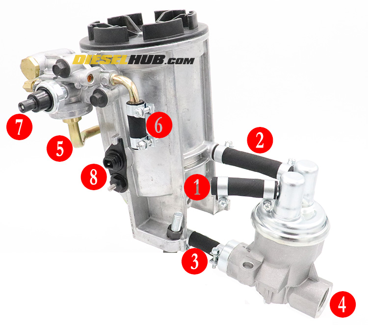
Referencing figure 1 (above), fuel is drawn from the tank (1), into the diaphragm chamber, and pumped into the fuel filter housing (2). This fuel is unfiltered and at a low pressure as it exits the pump (5 to 10 psi). Filtration occurs inside the filter housing and any fuel that is drawn into the high pressure chamber (3) of the fuel pump must first pass through the filter element. The piston inside this chamber ramps up the fuel pressure to 45-55 psi as it exits (4) into a pair of metal hard-lines (not pictured) that distributes fuel between the left and right cylinder heads.
A network of galleries in each cylinder head supply fuel to each fuel injector. Return lines connect the fuel pressure regulator to the front-most section of the cylinder head fuel galleries such that excess fuel is returned to the regulator. The pressure regulator bleeds off extra fuel back to the fuel tank (6) by means of a simple spring loaded plunger; the stiffness of this spring is what dictates actual fuel pressure. A portion of the fuel that is returned from the cylinder heads is also screened and directed back (5) to the lower outlet of the housing to be drawn into the fuel pump once more (3).
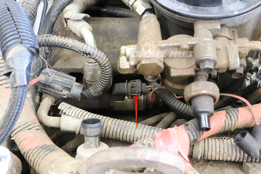
Fuel is drawn through the filter and into the pump (3) through a standpipe in the filter housing. This means that fuel is drawn from the upper portion of the housing, not the lowest point. Since water is heavier than diesel fuel and sinks, it collects in the sump of the filter housing. Contact will be made across the terminals of the water-in-fuel sensor (8, lower) if enough water collects in the bottom of the bowl. The fuel bowl assembly also incorporates a fuel restriction sensor (7) and fuel heater element (8, upper).
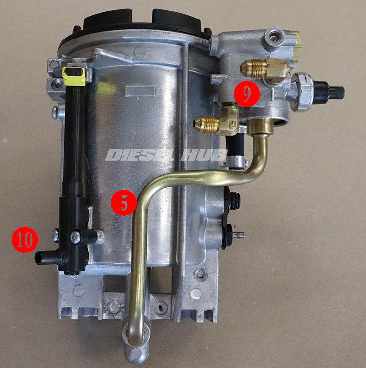
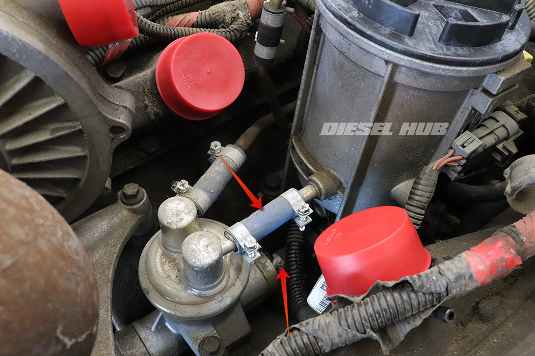
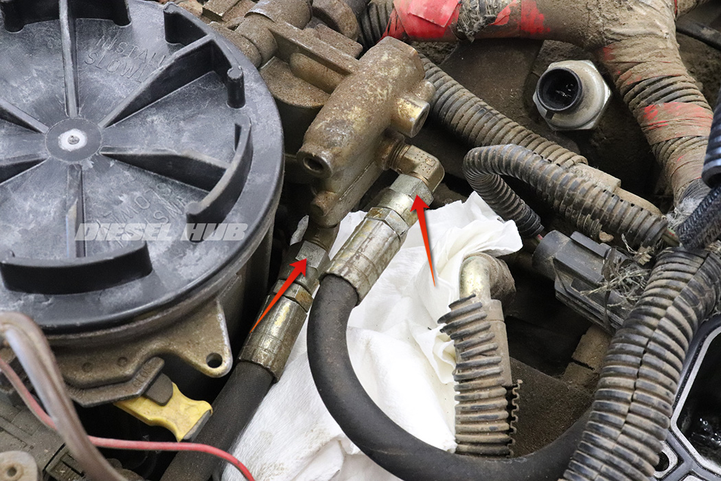
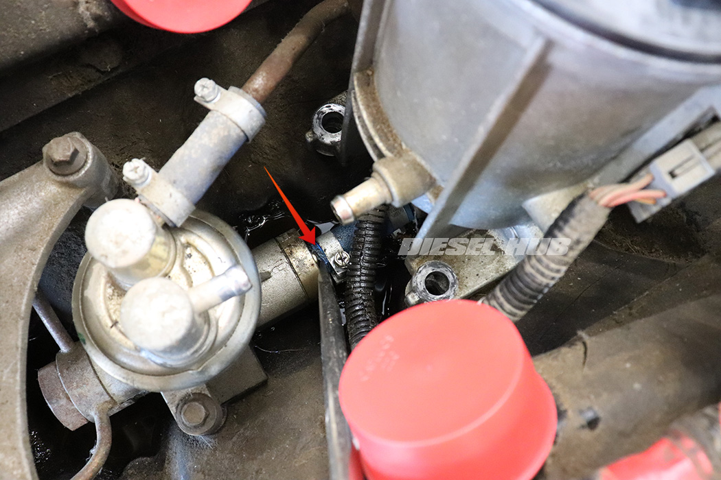
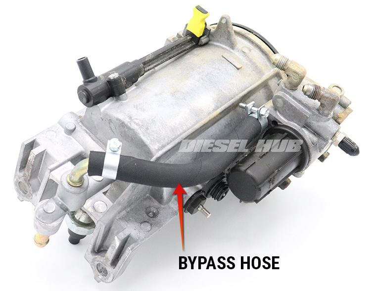
Item (9) in figure 2 above are the return line fittings for the left and right cylinder heads. Note that all the low pressure connections into and out of the fuel bowl are made with flexible hose and clamps, while all the high pressure connections are threaded. On 1994 and 1995 model year fuel bowls, the bypass hose (5) is flexible, not solid, and there is a serviceable mesh screen hanging from the pressure regulator.
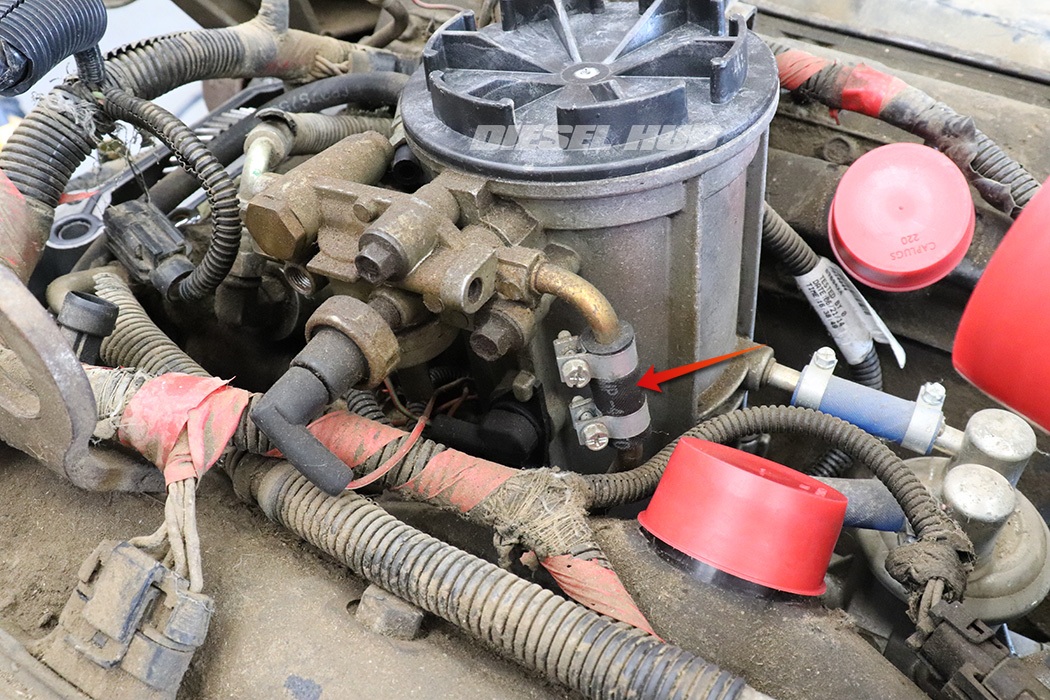
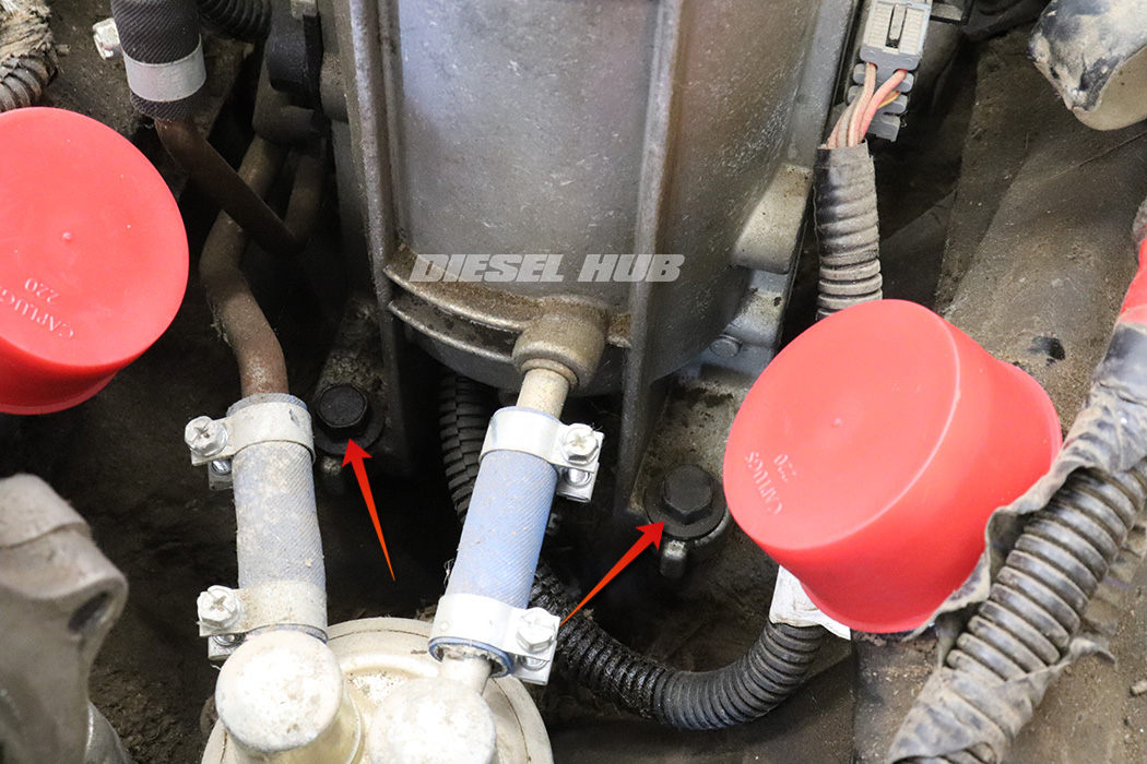
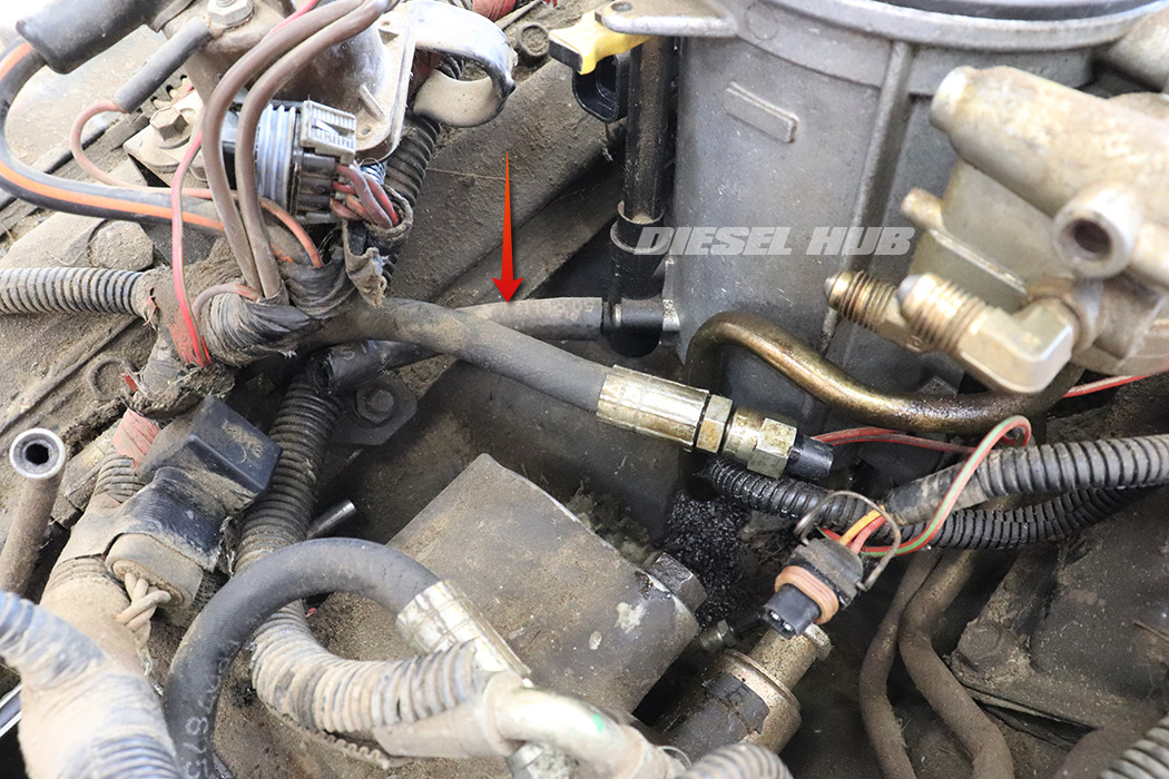
Item (10) is the fuel bowl drain, which connects to a metal hard-line that runs through the engine valley and down the front, passenger side of the engine (figure 3 below). When the yellow handle on the valve is turned 90 degrees, fuel will drain through this hard-line.
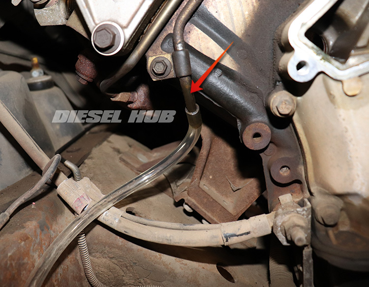
If a container is not placed beneath this hose, fuel will drain onto the frame, front steering components, and ground wire before finding the floor below. A 5/16 inch ID hose can be attached to the metal hard-line to extend its location so that a container can be positioned on the ground for easy draining. When not in use, it can be tucked into the frame or a nearby member for safe keeping.
Fuel Filter Housing Parts
| Component | Part Number(s) | Remarks | |
|---|---|---|---|
| Fuel bowl assembly | 1994-1995 | Motorcraft FG-1052 | [1] |
| 1996-1997 | Motorcraft FG-1054 | ||
| Wiring harness | Ford F7TZ-9S277-AA | [2] | |
| Fuel filter cap | Ford F5TZ-9G270-A | --- | |
| Fuel filter element | Motorcraft FD-4595 | --- | |
| Drain valve | Ford F5TZ-9A153-A | --- | |
| Hose kit (install kit) | Dieselply DP-1637K | [3] | |
| Bypass hose | Dieselply DP-163601 | [4] | |
| Return hoses | Driver | Ford F4TZ-9D308-A | --- |
| Passenger | Ford F4TZ-9B273-A | ||
| Updated fuel pressure test port | Dieselply DP-160401 | [5] | |
[1] - The later, more common FG-1054 for 1996 and 1997 model year engines is entirely compatible with the 1994 and 1995 engines. If the filter housing is to be replaced, we recommend upgrading to this style.
[2] - The IPR valve connector is integral to this harness and thus it is important to have good connections to the main wiring harness; replace is damaged or deteriorating
[3] - OEM hoses under an aftermarket label
[4] - This part is obsolete and no longer produced by Ford
[5] - Converts old Ford style fuel pressure test port to 1/4 inch flare, which is a common size for modern test gauges
How to Remove the Fuel Filter Housing
Click any thumbnail to view fullsize, detailed image
- Disconnect both negative battery cables.
- Drain the fuel bowl into a suitable container.
- Loosen the fuel bowl cap with an appropriate tool (recommend OTC 6760).
- Once the housing has drained completely, close the drain valve latch.
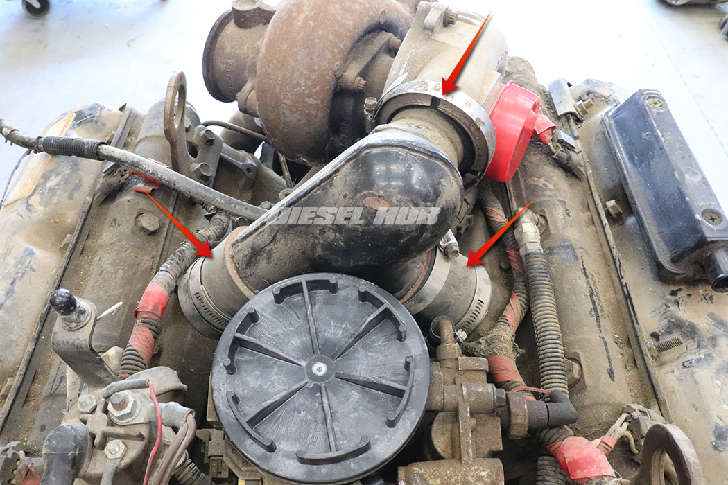
- Loosen both clamps on the intake boots on both sides (connects the intake "Y" to the left and right bank intake plenums).
- Loosen, then remove the hose clamp that secures the turbocharger compressor outlet to the intake "Y" adapter.
- Remove the intake "Y" and set aside. Cap or cover both intake plenum openings and the turbo compressor outlet.
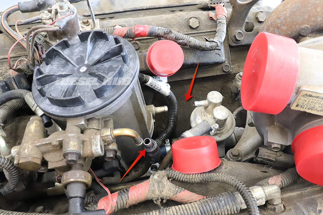
- Completely loosen the clamps on the fuel tank return hose (fuel filter housing pressure regulator to hard-line, 5/16 inch ID hose).
- Completely loosen the clamps on the hose that connects the passenger side upper fuel pump port to the fuel bowl.
- Completely loosen the clamps on the hose that connects the lower fuel pump port to the bottom of the fuel bowl.
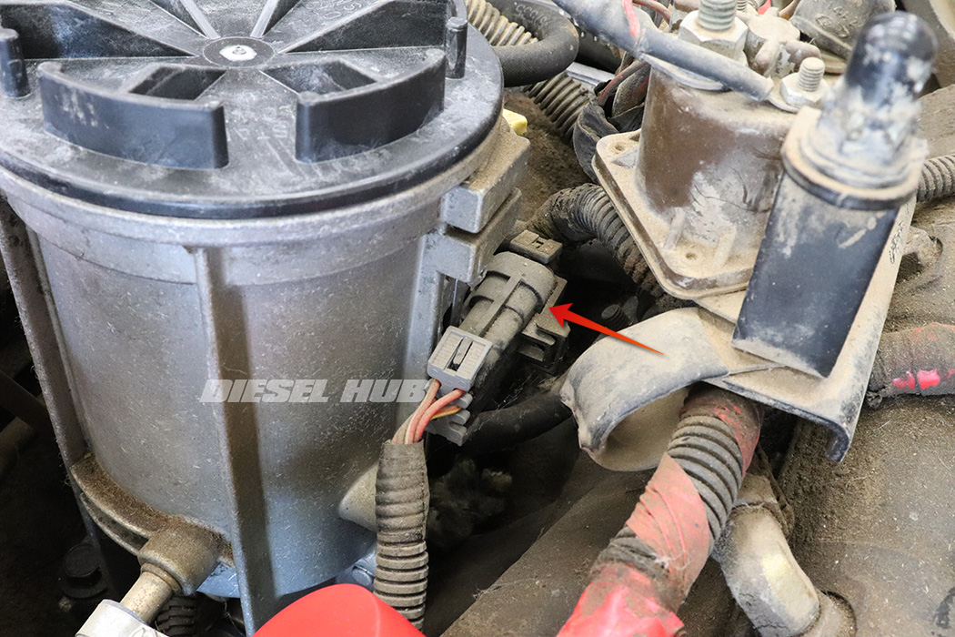
- Disconnect the large connector mounted to the passenger side of the fuel filter housing.
- Disconnect the IPR valve connector.
- The IPR valve is located beneath the fuel pressure regulator and mounts into the high pressure oil pump housing on the driver side.
- Loosen, then completely unthread the fuel hoses at the pressure regulator with a 9/16 wrench.
- These hoses return pressurized, filtered fuel to the bowl.
- Inspect the hoses for cracks and damage; compromised hoses should be replaced.
- Plug the hose fittings with clean caps once they are removed at the pressure regulator. Any contaminants that enter these hoses will wind up in the fuel galleries in the cylinder head; fuel from these lines is screened, but not filtered before it re-enters the fuel pump.
- Remove the (2) mounting bolts at the base of the fuel bowl assembly with a 13 mm socket.
- Work the short hose at the fuel pressure regulator down the hard-line.
- Completely remove the hose that connects the upper passenger side fuel pump port to the fuel bowl. At this point, the filter housing can be moved forwards as necessary to completely remove the hose.
- Tilt the filter housing back towards the turbocharger and disconnect the fuel bowl drain valve hose.
- This hose connects the drain valve to the metal hard-line that travels down the front of the engine.
- This hose is not secured with clamps and carries no pressure.
- Push the filter housing towards the front of the engine and work the last hose off (bottom of fuel pump to bottom of bowl).
- A long flathead screwdriver works well in prying the hose off the fuel pump.
- Maneuver the fuel bowl out of the engine compartment.
- Clean up any fuel that has collected in the engine valley. Ideally, the engine valley should be cleaned so that future leaks are more readily detected.
- If the fuel bowl is to be stored for any period of time, plug each of the various ports with vacuum caps to prevent dust and debris from infiltrating the system.
Filter Housing Installation
Installation of the fuel bowl is in reverse order. All the connection hoses between the filter housing, the fuel pump, and the fuel tank hard-lines should be replaced. However, it is not uncommon to reuse the drain valve to hard-line hose if it is in acceptable condition; this hose holds no pressure and only touches fuel when the bowl is drained. If it appears compromised or suspect, replace it to prevent leaking fuel into the engine valley.
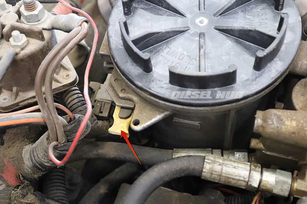
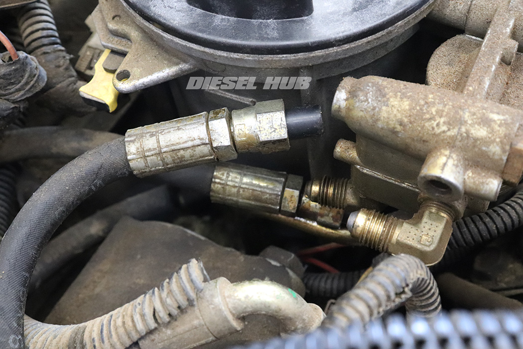
These hoses are available as an entire kit (see DP1637K for OEM hose kit). 1994 and 1995 fuel bowls utilize a flexible bypass hose (figure 4 below) which is not included in the standard kit. Ford has discontinued this hose, but OEM equivalents remain available (see DP163601). Do not attempt to supplement any of these hoses for standard auto parts store fuel hose - the OEM hose has a high temperature rating, pressure rating, and is significantly more resilient to biofuels.
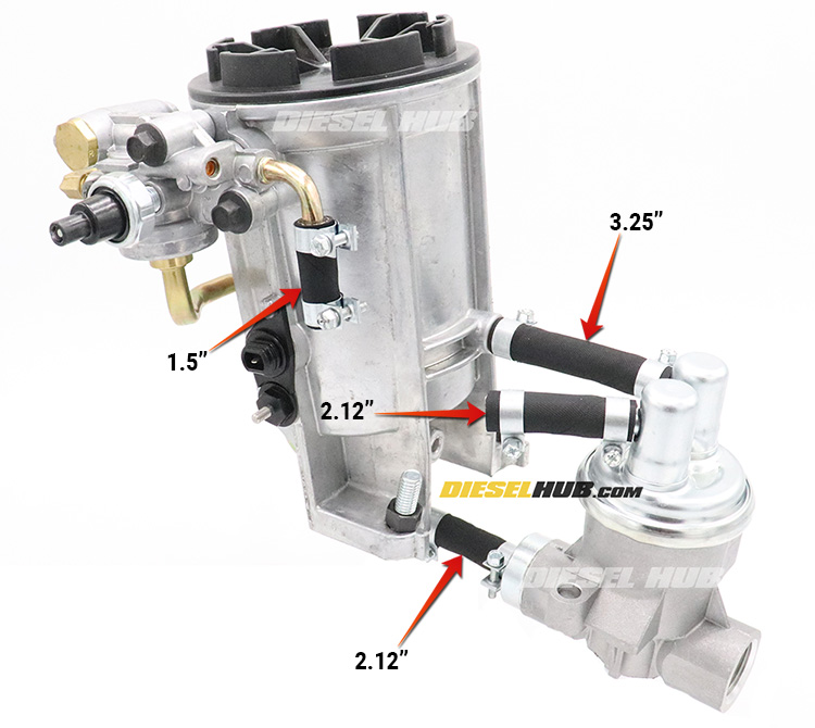
Install the hose at the bottom port of the fuel bowl first, then maneuver the housing into position in the engine valley and attach the other end of this hose to the fuel pump. There will be enough "wiggle room" in the filter housing to position back-and-forth as needed to secure the remaining hoses. Once all the slip-on hoses have been installed in the correct position, install the mounting bolts and secure it to the engine valley. The last hoses to be installed should be the two return lines at the front. Figure 5 (below) correctly identifies the hose lengths for each location.
Don't forget to install a new fuel filter once the housing has been reinstalled. If the engine valley was cleaned while the bowl was removed from the engine, leak detection will be that much easier. As a final word of advice, make sure to position the hose clamps such that they remain accessible in the installed position. Before starting the engine, prime the fuel system to prevent injector damage.

