
The 5R110W TorqShift is a five speed automatic transmission designed, developed, and manufactured by Ford Motor Company for various fullsize vehicles, notably the Super Duty pickup and chassis cab truck series. It was introduced for the 2003 model year as both an evolution of and replacement for the company's 4R100 four speed transmission. 5R110W transmissions are found in 2003 to 2010 Ford F-250, F-350, F-450, and F-550 Super Duty trucks. Engines that utilized the 5R110W include the 6.0L Power Stroke, 6.4L Power Stroke, 5.4L Modular V8, and 6.8L Modular V10. Although it was first introduced during the 2003 model year, this transmission was never offered with the 7.3L Power Stroke engine.
The TorqShift namesake would be carried over to Ford's six speed evolution, the 6R140 TorqShift transmission, for its 2011 model year debut. A 10 speed TorqShift transmission, the 10R140, would complete the evolution with a 2020 model year introduction.
Hot & Cold Modes
The 5R110W, although designated as a five speed automatic transmission, actually has six accessible forward gear ratios (refer to gear ratios in table 2). Under ordinary operating conditions, the transmission shifts 1st - 2nd - 3rd - 5th - 6th. However, in instances where the transmission fluid temperature is below 5 °F an alternative shift sequence is commanded which shifts 1st - 2nd - 3rd - 4th - 6th.
The standard shift schedule utilizes a 1 to 1 fourth gear ratio while the cold weather shift schedule engages a marginally shorter 1.09 to 1 ratio in an effort to bring the transmission fluid to operating temperature in less time. The effectiveness of this process is bolstered by holding gears longer, allowing the engine to reach higher speeds than it would normally under the same inputs.
Specifications
| Manufacturer | Ford Motor Company | |
|---|---|---|
| Designation(s) | 5R110W TorqShift | |
| Type | 5 speed automatic, rear wheel drive | |
| Predecessor | Ford 4R100 4 speed | |
| Successor | Ford 6R140 TorqShift 6 speed | |
| Applications | 2003 - 2010 Ford F-250, F-350, F-450, F-550 Super Duty (pickup & chassis cab trucks) 2003 - 2005 Ford Excursion 2004 - 2010 Ford Econoline E-350, E-450 |
|
| Production Plants | Ford Motor Company Sharonville Transmission Plant, Sharonville, Ohio | |
| Overall Ratio/Ratio Spread | 4.38 | |
| Gear Ratio Range | 3.11 - 0.71 | |
| Average Gear Step | 45% | |
| Control Type | Electronic | |
| Max Input Torque | 1,100 N-m (811 lb-ft) | |
| Case Material | Aluminum | |
| Weight | Approximately 300 lbs with fluid | |
| PTO Provisions | Stationary and mobile operation, requires option 62R [1] - driver side access, non-standard 6 bolt provision |
|
| Max PTO Output | 250 lb-ft [2] | |
| Service Interval | 2003 - 2008 | Replace transmission fluid, sump filter, and remote filter every 30,000 miles |
| 2009 - 2010 | Replace transmission fluid, sump filter, and remote filter every 60,000 miles | |
| Fluid Type/Spec | Motorcraft MERCON LV automatic transmission fluid [3] | |
| Fluid Capacity | Approximately 17.5 quarts [4] | |
| Sump Filter | 2003 - 2007 | Motorcraft FT-144 |
| 2008 - 2010 | Motorcraft FT-180 | |
| Remote Filter | Motorcraft FT-145 | |
| Pan Gasket | Ford F6TZ-7A191-A | |
[1] - PTO is not standard on all TorqShift transmissions, option 62R required
[2] - Minimum PTO operating speed is nominally 1,200 rpm
[3] - MERCON LV is the correct replacement for the original MERCON SP; MERCON SP production ceased in 2023 (see TSB 51909)
[4] - Total system capacity for most applications; fluid required during basic service will vary
Gear Ratios
| Gear Number | Ratio (:1) |
|---|---|
| 1st | 3.11 |
| 2nd | 2.20 |
| 3rd | 1.54 |
| 4th [5] | 1.09 |
| 5th | 1.00 |
| 6th | 0.71 |
| Reverse | 2.88 |
[5] - 4th gear ratio is a function of the cold weather shift schedule only. Transmission shifts 1-2-3-5-6 when transmission fluid temperature is greater than 5 °F, 1-2-3-4-6 when transmission fluid temperature is 5 °F or below.
| Shift Sequence | Step (%) |
|---|---|
| 1st to 2nd | 41% |
| 2nd to 3rd | 43% |
| 3rd to 5th | 54% |
| 5th to 6th | 41% |
Features
The 5R110W is notable for its sophisticated electronic controls and wear compensating adaptive shift strategy. Its integrated "Tow/Haul" mode is also a particularly popular feature for 6.0L Power Stroke applications as this shift strategy was able to use the variable geometry turbocharger as an engine braking device. Leveraging this with well-timed downshifts results in an operating mode that will maintain speed on descents and help slow the vehicle with less reliance on the service brakes while towing.
Adaptive Strategy
The 5R110W TorqShift transmission utilizes an adaptive engagement schedule referred to as the "adaptive strategy". This system is often incorrectly perceived as one that "learns" driving habits and behaviors to create an individualized shift schedule. On the contrary, the goal of the system is to compensate for wear and maintain shift quality as the transmission ages.
This is accomplished by means of a perpetual process that evaluates each shift. The time taken to complete a shift is measured, compared to a predetermined "ideal" value for the operating conditions, and the shift schedule (pressure and timing) is adjusted accordingly. Matching the actual real-world shift time to the ideal or expected values through optimization of shift parameters is the primary objective of the adaptive strategy.
To create a comprehensive shift schedule the transmission must experience a variety of load and speed combinations over each up-shift and downshift sequence. When the keep alive memory (KAM) is cleared from the PCM, it loses all stored information for the adaptive strategy. As such, the shift schedule needs to regenerate anytime the PCM loses power for an extended period of time (i.e. both batteries are disconnected) or it has been re-flashed.
It is not uncommon for the transmission to exhibit crude and unpredictable behavior or harsh engagements for a period of time after the KAM has been reset. The PCM will eventually "re-learn" its shift schedule parameters through normal driving because this program runs perpetually, but the process may be expedited by performing a series of manual procedures and meeting certain criteria. These procedures are as follows:
- Bring the engine and transmission to normal operating temperature.
- Idle the engine for a minimum of 1 minute with all accessories off.
- Idle the engine for a minimum of 1 minute with the air conditioning turned on.
- While driving the vehicle, allow the transmission to progress through each gear (1st to 2nd, 2nd to 3rd, etc) with light accelerator input.
- While driving the vehicle, allow the transmission to progress through each gear with moderate accelerator input.
- While driving the vehicle, allow the transmission to progress through each gear with heavy accelerator input (wide open throttle).
- With the vehicle stopped and the gear selector placed in the neutral (N) position, perform the following sequences (order is not important):
- Shift from neutral (N) to reverse (R), then wait a minimum 3 seconds.
- Shift from reverse (R) to drive (D), then wait a minimum 3 seconds.
- Shift from drive (D) to neutral (N), then wait a minimum 3 seconds.
- Repeat this series of actions with the "Tow/Haul" mode activated.
While following these procedures will potentially reduce the re-learn time of the adaptive strategy system, it may take several hundred miles or more of actual drive time before shift behavior is optimized.
Tow/Haul Mode
The 5R110W transmission features an integrated "Tow/Haul" mode that can be activated via a shifter mounted switch in lieu of the overdrive lockout switch that earlier transmissions used. When activated, the "Tow/Haul" light on the shift handle is illuminated. When selected, the transmission follows on alternative shift schedule and modifies the torque converter lockup strategy. Specifically, transmission downshifts and torque converter lockup will occur more aggressively while coasting as a means of slowing the vehicle down or maintaining vehicle speed on descents.
As part of the alternate shift schedule you may notice that the transmission holds gears longer, shifts at higher engine speeds, downshifts with increased sensitivity to accelerate pedal input, and the torque converter locks up assertively while braking. Many of the changes in shift pattern are dependent on engine load and thus the heavier the payload, the more aggressive the shift strategy. On vehicles equipped with the 6.0L Power Stroke diesel, the variable geometry turbocharger is used as an engine braking mechanism while the "Tow/Haul" mode is active.
Shift Solenoids
Since the 5R110W is a completely electronic transmission it does not have a traditional valve body and instead (7) solenoids are mounted to a manifold that is mounted to the underside of the transmission where a valve body would typically be located. These solenoids engage the correct combination of clutches to achieve each gear ratio. Additionally, there are solenoids that control the line pressure and torque converter lockup. Each solenoid and its location on the manifold (also "solenoid body") is identified in figure 2 below.
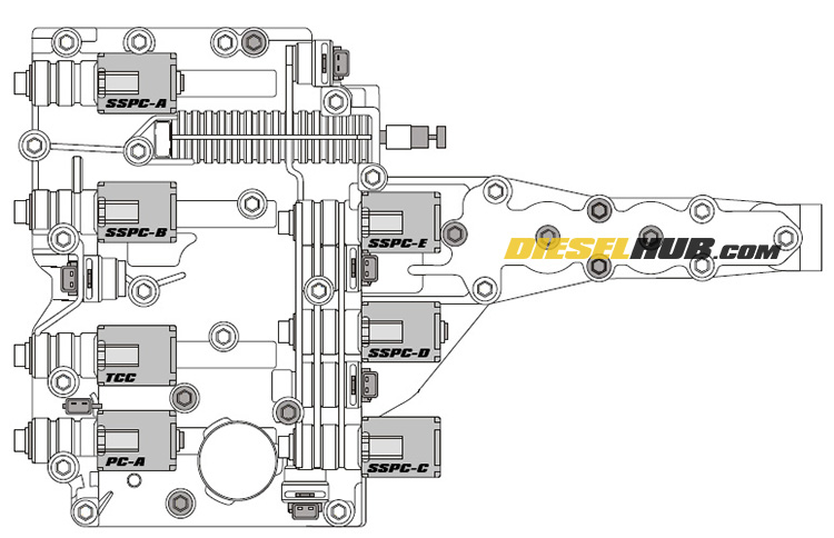
- PC-A : line pressure solenoid
- SSPC-A : shift solenoid A, coast clutch
- SSPC-B : shift solenoid B, overdrive clutch
- SSPC-C : shift solenoid C, intermediate clutch
- SSPC-D : shift solenoid D, direct clutch
- SSPC-E : shift solenoid E, low & reverse clutch
- TCC : torque converter clutch solenoid (lockup solenoid)
Directly vs Inversely Proportional
Take note that not all the shift solenoids are interchangeable and for the (7) solenoids there are three part variations. Each of the three different configurations has a unique mounting tab cast into the face of the solenoid that makes it impossible to install in the wrong location.
Directly proportional solenoids are normally closed and pressure is increased by increasing the amperage delivered across the solenoid terminals. Indirectly proportional solenoids are normally open and pressure is reduced by increasing the amperage delivered across the solenoid terminals. For a closer look at the shift solenoids, see: 5R110W TorqShift shift solenoid replacement. Additionally, table 4 below summarizes the shift solenoid type, part number, and its resistance range (for diagnostics).
| Solenoid | Type | Allowable Resistance | Part Number |
|---|---|---|---|
| PC-A | Inversely proportional | 5.1 - 5.8 Ω | 4C3Z-7G383-AA |
| SSPC-A | Inversely proportional | 4.1 - 4.7 Ω | 3C3Z-7J136-AA |
| SSPC-D | |||
| SSPC-B | Directly proportional | 4.1 - 4.7 Ω | 3C3Z-7J136-AB |
| SSPC-C | |||
| SSPC-E | |||
| TCC |
Basic Diagnostics
Problems with the 5R110W transmission can be roughly separated into two categories: mechanical and electrical. Mechanical problems include stuck/clogged solenoids, worn clutches, damaged gear sets, fluid leaks, etc. Electrical malfunctions include inoperable/failed shift solenoids, faulty/missing sensor input signals, a communication error between the transmission and PCM, etc.
Transmission specific DTCs do not illuminate the malfunction indicator light in the instrument cluster. Rather, transmission faults result in a blinking Tow/Haul light on the shifter. Certain DTCs will also send the transmission into limp mode, in which only the 5th and reverse gears will be available. It is sometimes possible to "reset" limp mode by turning the engine off, then restarting it. If the issue is detected once more it will enter limp mode again, but this method may work to get a stranded vehicle to a safer location.
Shift Solenoids
With the fluid pan removed it is relatively easy and straight forward to test each shift/pressure solenoid. After removing the respective electrical connector, measure the resistance across the two terminals with a digital multimeter. The acceptable values are listed in table 4 (above) and each solenoid is identified in figure 2 (above). If the resistance is found to be out-of-range, the solenoid should be replaced. These can be replaced individually and there is no reason to replace them as a set, particularly if only one solenoid is found to be bad.
Line Pressure Test
The line pressure test requires connecting a compatible test gauge to the transmission pressure port. The plug for the pressure port is located on the driver side of the transmission near the oil pan flange (figure 3, below). With the gauge installed, the tires chocked, the parking brake set, and the brake pedal fully depressed, the pressure is recorded at idle in each of the range positions and then again at stall speed.
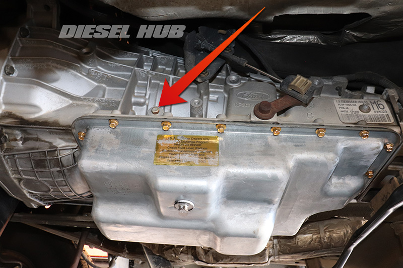
Use a hydraulic hose and gauge with a high enough rating to provide a reasonable factor of safety. For the stall speed test, the engine is brought to stall speed at WOT for no more than 5 seconds; this test places tremendous mechanical stress on the drivetrain and by its very virtue is relatively dangerous. Should there be any failure of the pressure test at idle in any range position, do not perform the stall speed test. Compare recorded pressure readings to the factory specifications in table 5 below.
| Range Position | Pressure @ Idle | Pressure @ Stall Speed |
|---|---|---|
| P, N | 50 psi | N/A |
| R | 100 psi | 320 psi |
| D | 70 psi | 320 psi |
| 3 | 80 psi | 260 psi |
| 2 | 215 psi | |
| 1 | 270 psi |


Editor, Diesel Hub