
Applicable Models:
2003 - 2007 Ford F-250, F-350, F-450, F-550 Super Duty
2003 - 2005 Ford Excursion
Applicable Engine(s):
6.0L Power Stroke V-8
Function & Operation
The horizontal fuel conditioning module (HFCM) contains the primary fuel filter, fuel pump, water-in-fuel sensor, water drain plug, and a thermal fuel recirculation device. 2003 and 2004 versions of the HFCM also included a fuel heating device; additional information on the "new" style HFCM is provided in a section below. The HFCM draws fuel from the tank, completes the initial stage of filtration, perpetually separates water from the fuel supply, and also contains a device that recirculates warm fuel under the correct conditions.
On Super Duty trucks (including Excursions) it is mounted inside the frame rail on the driver side of the vehicle at a distance that is just forward of where the transmission tailshaft is located. On a 4 wheel drive truck the front drive shaft impedes access to the HFCM, but it is still within reach for service and repairs. E-Series vans utilize an entirely different fuel conditioning module that eases access within the van chassis.
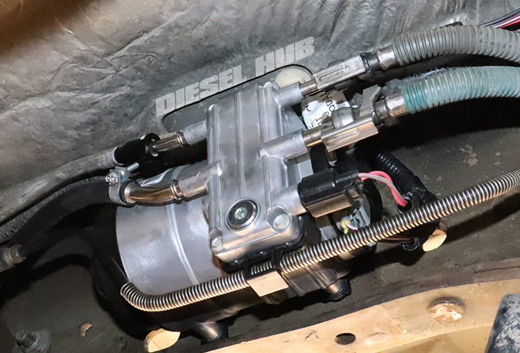
A series of chambers are incorporated into the accessible side of the HFCM housing. The lower chamber features a drain plug that allows the housing to be drained, both to remove water that has settled or to drain the housing for service. If the water level in the fuel-water separator reaches the water-in-fuel sensor, continuity is made across its terminals, a signal is sent to the PCM, and the operator is alerted of the condition at the instrument cluster. The primary fuel filter cap points towards the rear of the vehicle and is removed with a 36 mm socket.
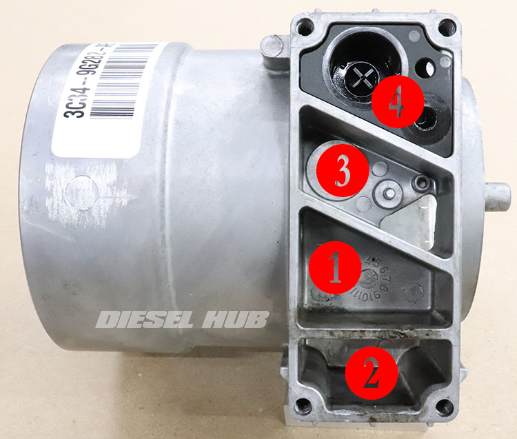
The two smaller diameter, upper tubes are the return lines while the two lower, larger diameter tubes are the suction and supply lines. With the small access cover removed, the four individual chambers are viewable. Referencing figure 2 (above), fuel is drawn from the tank and enters the chamber labeled "1". On early style modules, the fuel heater resides here and all fuel drawn into the housing passes across the heating element. Fuel is drawn from this chamber through a check valve and into the larger area where the fuel filter and fuel pump are situated.
Water is denser than diesel fuel and thus [ideally] settles to the bottom of the housing in the chamber labeled "2". The entire housing will be drained through this chamber when the exterior drain plug is removed. The water-in-fuel sensor is also positioned in this chamber and if enough water is collected, it will complete the circuit in this sensor and alert the operator via an instrument cluster display message.
The fuel pump draws fuel through the filter and pressurized fuel exits into the chamber labeled "3". Fuel then exits this chamber through the supply tube and travels to the secondary fuel filter, which is mounted next to the oil filter on the top of the engine. A pressure regulator incorporated into the secondary filter housing returns excess fuel to the HFCM.
Fuel that returns from the secondary filter housing enters the HFCM chamber labeled "4". Here, a thermostatic device decides whether the fuel is returned to the tank or to the primary filter compartment. This device works similarly to a typical cooling system thermostat. If the temperature of the fuel contained within the HFCM is less than 80 °F, the returned fuel is recirculated. If the temperature of the fuel in the HFCM is greater than 80 °F the device closes and fuel is returned to the tank instead.
Updated HFCM & Wiring Harness
For the 2005 model year the HFCM was redesigned with no fuel heater. This coincided with Ford's first nod of approval toward biodiesel. While there is no mention of biodiesel in the 2003 and 2004 diesel supplement guides, the 2005 version approves diesel fuel blends with up to, but no more than 5% biodiesel by volume. The early and late style HFCMs are easily distinguishable because the early units had (3) electrical connectors (water-in-fuel sensor, fuel heater, fuel pump). The later models only have (2) electrical connectors (water-in-fuel sensor, fuel pump).
It is common to see significant corrosion, pitting, and debris buildup in the heating chamber of the early style fuel conditioning modules due to biodiesel exposure. Pieces of the fuel heater assembly also frequently break off and are found loose in the chamber. One look at the heating device quickly reveals alloys that are not compatible with biodiesel, which provides justification for removing this component.
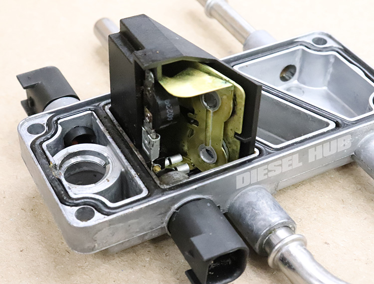
The general operation of the HFCM did not change, but the new design requires an alternate wiring harness. The new harness (Ford 6C3Z-9F759-A) does not have a connector for the fuel heater and replaces the previous section of harness that connects to the large, black chassis connector. It is plug-and-play in that older vehicles are easily retrofitted, but the updated harness is not compatible with the old style HFCM and visa versa.
Replacing Fuel Pump vs HFCM
If the primary goal is to replace the fuel pump, there are several options. The most economical pathway is to remove the HFCM and install a new fuel pump. The caveat is that the factory Parker/Racor fuel pump is 80% of the cost of a new HFCM. Aftermarket fuel pumps are available at a significant lower cost I cannot attest to the performance or service life of these alternatives.
If a new style HFCM is desired for 2003 and 2004 model year trucks, there are also two different options - replace the HFCM, or replace only the faceplate. The faceplate is what contains the fuel heater, thus installing a new style faceplate on an old style housing essentially leaves you with the updated HFCM at a reduced cost.
Ultimately, you will have to weigh the cost of the options that meet your needs. The parts list below (table 1) provides part numbers for the various components related to the fuel pump and fuel conditioning module.
Applicable Parts
| Component | Part Number(s) | Remarks |
|---|---|---|
| HFCM assembly | Ford 6C3Z-9G282-D | [1] |
| HFCM wiring harness | Ford 6C3Z-9F759-A | [2] |
| HFCM faceplate | Ford 6C3Z-9B249-A | [3] |
| Fuel pump | Racor PFP58054 Delphi HFP964 |
[4] |
| Fuel filter set | Motorcraft FD-4616 | --- |
| Upgraded drain plug | Ford 6E7Z-9C082-A | [5] |
| Fuel pressure test fitting | DP-161501 | [6] |
| Pressure regulator kit | Ford 3C3Z-9T517-AG | [7] |
[1] - Updated version without fuel heater
[2] - Updated wiring harness without fuel heater connection; required if upgrading to new style HFCM/faceplate
[3] - Faceplate without fuel heater; can replace faceplate and fuel pump independently to convert to the new style without replacing the entire HFCM (cost effective)
[4] - Fuel pump is included with HFCM assembly, can be serviced separately; Racor is the OEM pump manufacturer
[5] - Upgraded drain plug has convenient amenities including a knurled circumference and a tang that allows it to hang while draining (less fuel splash)
[6] - Test fuel pressure after replacing HFCM/fuel pump before starting engine
[7] - Low fuel pressure may be indicative of a collapsed pressure regulator spring; kit includes all necessary seals
How to Remove & Install the HFCM
Click any thumbnail to view fullsize, detailed image
- Disconnect both negative battery cables.
- Loosen the cap for the secondary fuel filter (mounted to the engine) with a 24 mm socket. It does not need to be removed entirely, but needs to allow air to displace fuel in the lines as it drains from the HFCM.
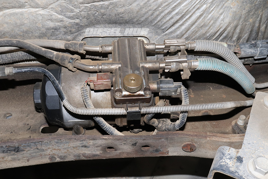
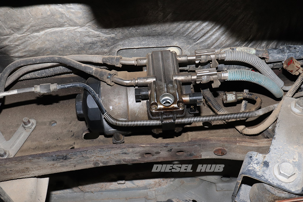
- Locate the HFCM mounted inside the driver side frame rail. On a four wheel drive truck, it is positioned just forward from the transfer case front output shaft.
- Unplug each electrical connector from the HFCM. On an old style unit, there are a total of (3) connectors (water-in-fuel sensor, fuel heater, fuel pump). On a new style HFCM there are only (2) connectors (water-in-fuel sensor, fuel pump).
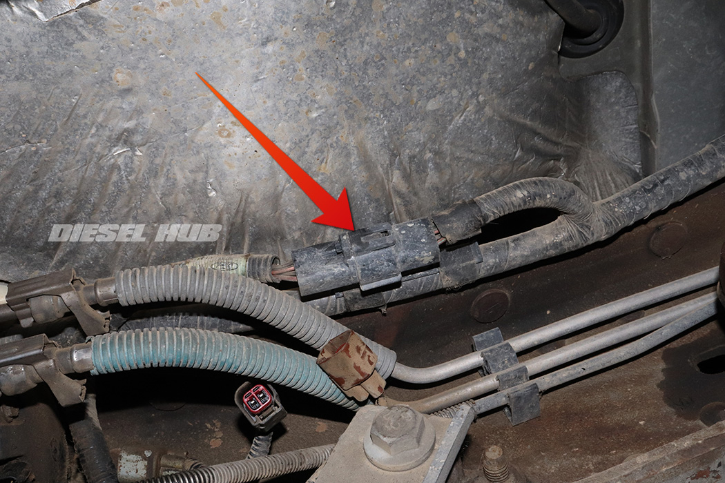
- Trace the HFCM harness until you find a large black connector just forward of the fuel pump. Press the locking tab and pull the two connector halves apart to separate.
- Maneuver the entire fuel pump harness off the vehicle.
- Removing this section of harness entirely prevents it from getting soaked in diesel fuel.
- Place a suitable container beneath the HFCM drain plug.
- Place a generous amount of shop rags between the HFCM and frame rail.
- Remove the HFCM drain plug with a 6 mm hex driver (Allen).
- Once the HFCM has drained, remove the fuel filter cap at the rear of the unit with a 36 mm socket.
- Remove the fuel filter and replace the cap loosely.
- Replace the drain plug once it has drained completely.
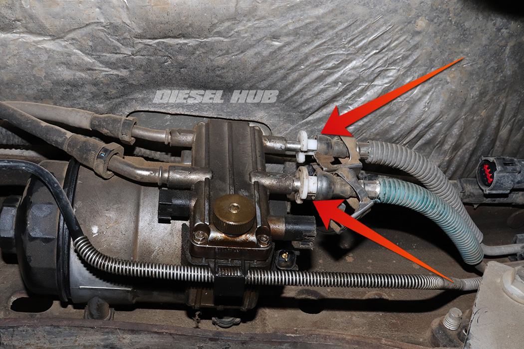
- Unclip the safety latches on the front two fuel line fittings.
- Remove the fuel supply quick connect fitting (HFCM outlet to engine) by installing a 3/8 inch fuel line tool. Push the tool into the fitting while simultaneously pushing the fitting into the tool to release the locking clips, then pull the fitting away from the tube.
- Repeat for the fuel return line (engine to HFCM return).
- Do not attempt to remove these fittings without the proper tool(s) as the spring clips can be damaged.
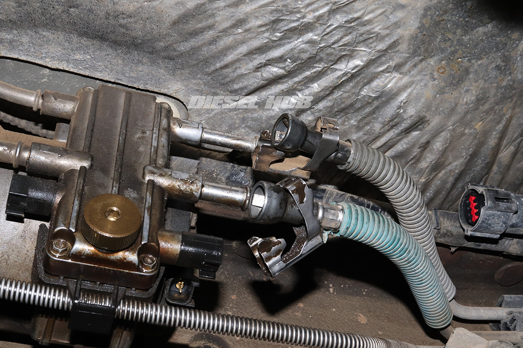
- If you have never used these tools it may take a few attempts to get a "feel" for how they work. Do not over-complicate this procedure, it is quite simple - the tool bends a series of small metal tabs inside the fitting upwards so that it can slide over the flange on the tube.
- Once removed, allow the fuel lines to drain completely. If desired, they can be plugged with vacuum caps (recommended).
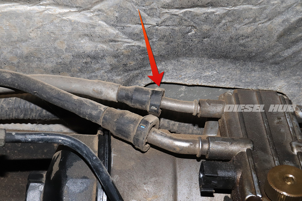
- The supply and return lines at the rear of the HFCM also use quick connect fittings but require no tools for removal. Locate the blue or white tab on one side of the fitting and depress it firmly, then pull the fitting off the tube.
- Do not pry or insert anything into the fitting as it may damage the locking tab - spin the fitting, locate the colored tab, and press to unlock.
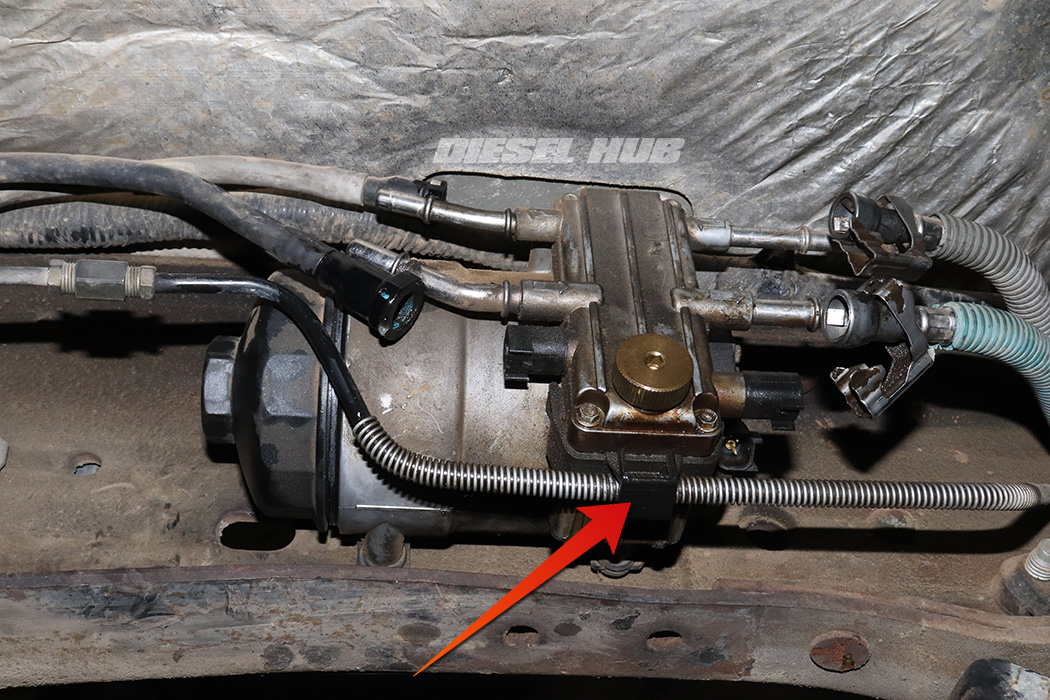
- Let the rear supply and return lines drain. It is possible for the supply (large) line to siphon from the tank, especially if it is full of fuel. If this occurs, install a small vacuum plug in it to prevent fuel from flowing indefinitely.
- Maneuver the plastic bracket beneath the drain plug to free it from the hard line it supports.
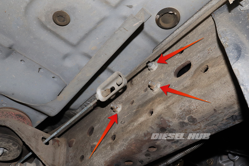
- Locate the HFCM mounting nuts on the opposite side of the frame rail.
- Remove the (3) nuts with a 13 mm socket while supporting the HFCM.
- Maneuver the HFCM out from the frame rail. It will drain additional fuel, so have shop rags handy and a container to set it in.
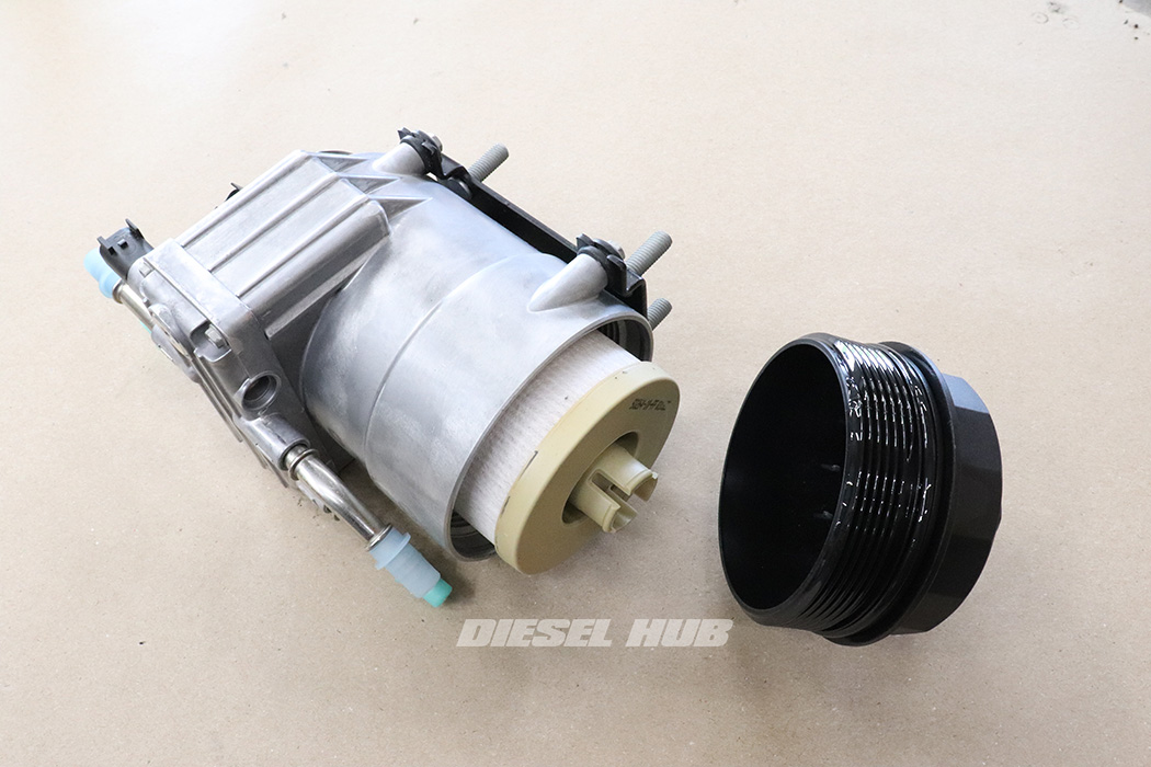
- If the HFCM is being replaced, make sure the new part has a filter! The new Ford HFCM should come with a filter installed, but it is good practice to verify it is in place instead of assuming.
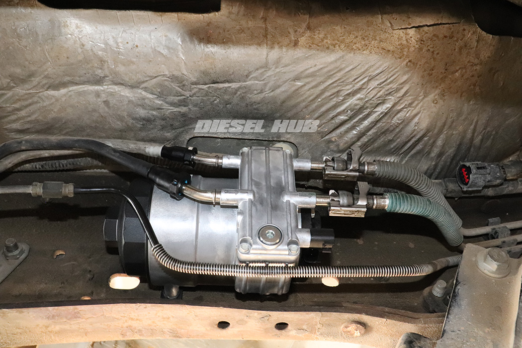
- Maneuver the HFCM into place and install the mounting nuts loose to make it easier to reinstall the hoses.
- Reinstall all (4) fuel lines - no special tools are needed, they will "snap" into place as they are pressed over the tube.
- Tug on each fuel line to ensure that the fittings locked properly.
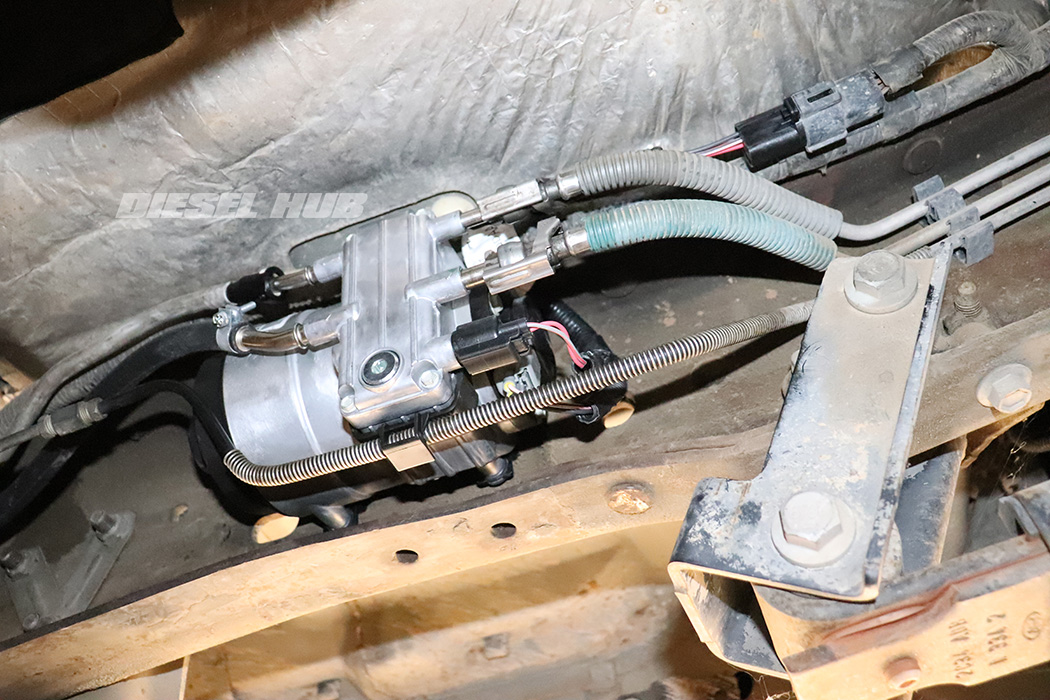
- Tighten the HFCM mounting bolts.
- Install the plastic bracket beneath the drain plug.
- Clean any fuel spills and verify that the filter cap is torqued to 19 lb-ft (25 N-m).
- Install the wiring harness, making sure that each connector properly latches.
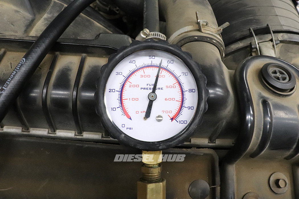
- Bleed the fuel system by turning the key to the "RUN" position until the fuel pump stops running (approximately 20 seconds). Repeat 10 to 12 times before attempting to start the engine. Check for leaks while the pump is running and system is under pressure.
- I highly recommend connecting a fuel pressure gauge to the secondary filter housing to verify fuel pressure. Fuel pressure will stabilize (minimal up-and-down) when air is properly bled from the system.
- Alternatively, the fuel pump can be commanded "ON" using a scantool. I prefer this method because it will run continuously until turned "OFF" (figure 4, below).
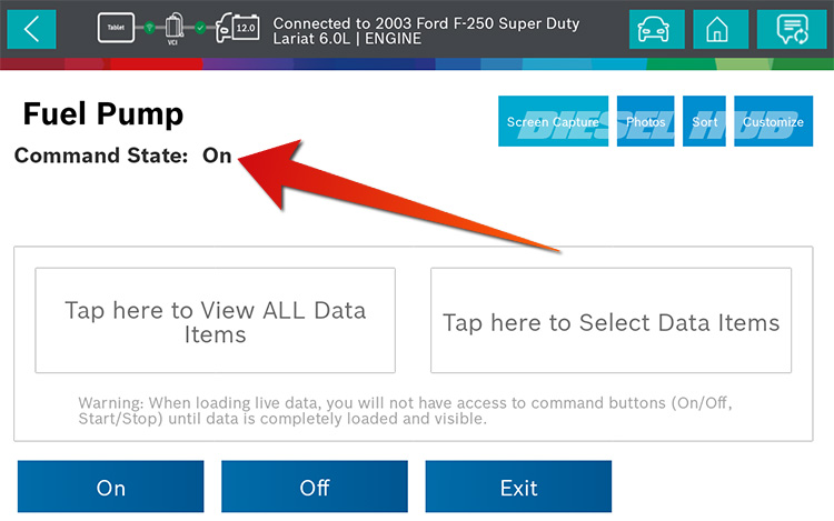
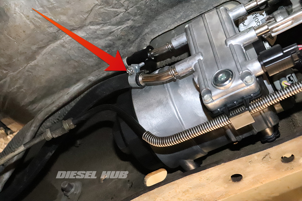
- Broken quick connect fittings at the rear of the unit (supply from tank and return to tank) can be repaired by tracing the hose back to the rigid line and cutting out the flexible hose section (approximately 12 inches worth).
- Replace with a section of flexible fuel hose with clamps at either end.
- Use 3/8 inch hose for the supply line and 5/16 inch hose for the return line. This is a common repair as the quick connect fittings are not always readily available.
How to Replace the Fuel Pump
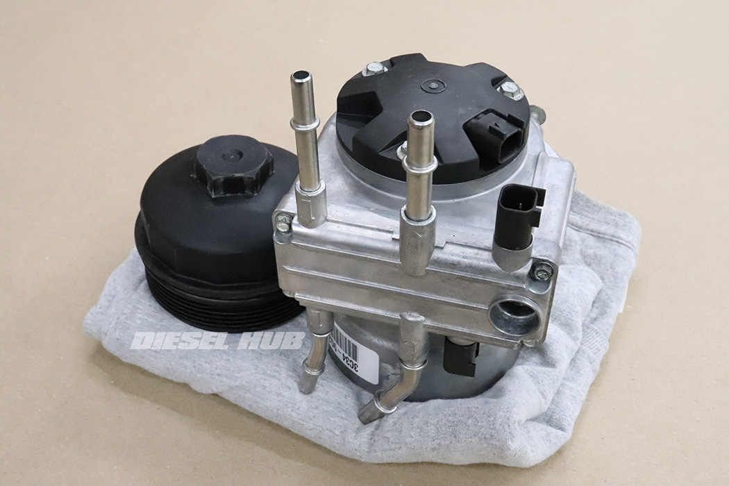
- Remove the HFCM from the vehicle (from previous procedures above).
- Remove the cap and fuel filter.
- Let the HFCM rest on some shop towels to drain completely.
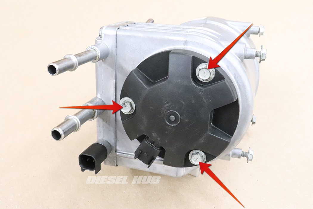
- If desired, mark the orientation of the fuel pump electrical connector on the housing - if the connector is positioned incorrectly, it may be difficult to reinstall the connector.
- Remove the (3) screws securing the fuel pump to the housing with a 5/16 inch socket.
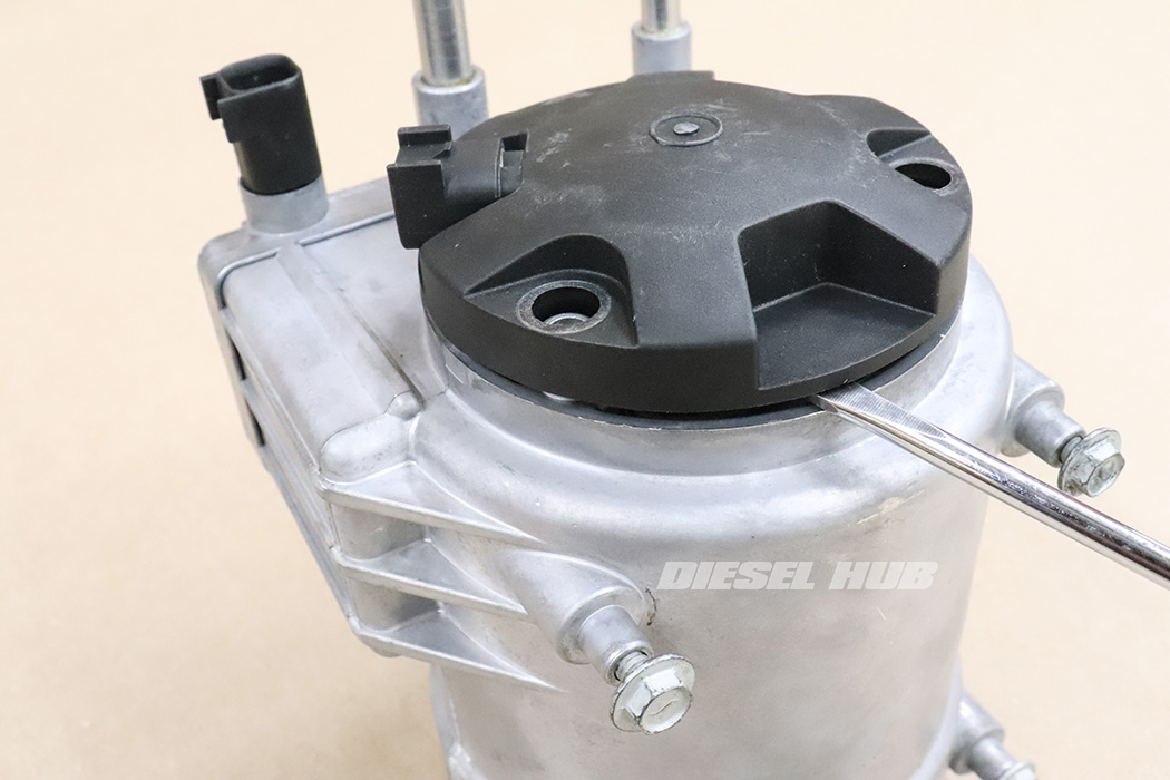
- Carefully remove the fuel pump from the housing. I find that gently prying while pushing from inside the housing is an efficient way to break free stubborn o-ring seals. You may also find that rotating the pump while pulling it out of the housing is useful.
- Do not pry excessively and/or mar the sealing surface of the housing.
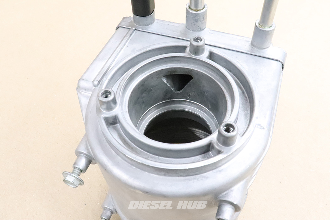
- As necessary, clean the o-ring sealing surfaces. They should be clean and free of old material and any debris that would prevent a positive seal. The two upper o-rings on the fuel pump assembly seal the pressure chamber from the suction side and exterior of the housing. A poor seal may result in pressure loss and/or an external leak.
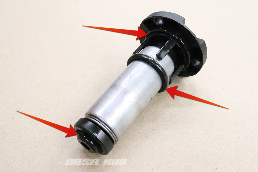
- Generously lubricate all (3) o-rings on the new fuel pump assembly with clean motor oil.
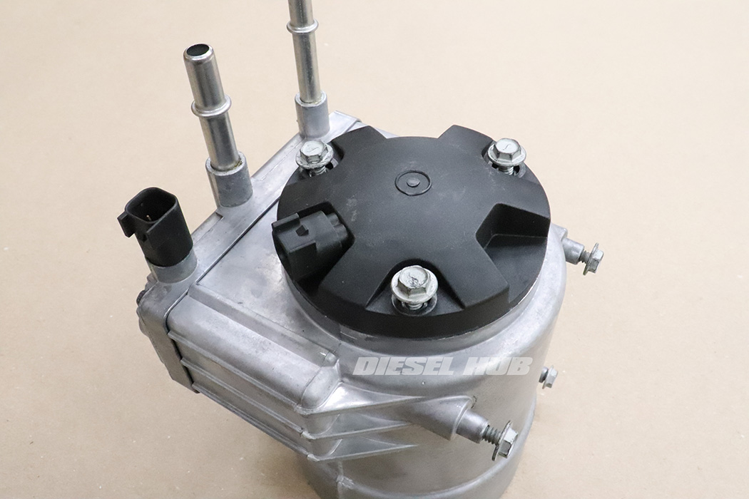
- Install the fuel pump in reverse order, noting the orientation of the fuel pump connector so that it is not difficult or impossible to install the harness connector.
- Reinstall the HFCM, wiring harness, and install a new fuel filter.
- Cycle the key to the "ON" position until the fuel pump turns off, then position the key to the "OFF" position. Repeat this process roughly 10 to 12 times to bleed air from the system. If the engine stutters and stalls upon initial startup, repeat the priming process several more times.
- Alternatively, a scantool can be used to power the pump "ON" for as long as necessary, negating the need continuously cycle the key (as previously depicted in figure 4 above).
- Replace the secondary (engine mounted) fuel filter after verifying that the engine starts/runs normally, fuel pressure is within specification, and there are no leaks.


Editor, Diesel Hub