Applicable Models:
1988 - 1994 Ford F-250, F-350, F-Super Duty trucks
1988 - 1994 Ford E-250, E-350 vans
Applicable Engine(s):
International Navistar 7.3L IDI V-8
(naturally aspirated & turbocharged variants)
Delete Kit:
The fuel bowl heater is a simple resistive heating element positioned inside the fuel filter base on all 7.3L IDI engines (this device is not found on 6.9L IDI engines). Its purpose is to keep fuel in the filter assembly above the waxing temperature and/or "melt" waxed diesel fuel to maintain operation in extremely cold weather. Fuel waxing (also referred to as gelling) materializes when naturally occurring paraffin waxes in diesel fuel crystallize in cold temperatures, thickening the fuel and making it difficult or impossible to pump. The crystallization of diesel fuel also has the propensity to clog fuel filters.

The temperature at which diesel fuel begins to wax is called the cloud point and depends on several factors, including the type of fuel and its paraffin content. #1 and winterized (a blend of #1 and #2) diesel fuels have a lower cloud point and thus can resist waxing better than standard #2 diesel fuel. Fuel quality can also be a critical factor in the cloud point of diesel. #2 diesel fuel can exhibit a cloud point as high as 20° F while #1 diesel fuel can exhibit a cloud point as low as -40° F (on average). Most localities switch to #1 or winterized fuel blends prior to winter, but this is largely dependent on the local weather outlook.
The cloud point of diesel fuel can be significantly lowered through treatment with an appropriate fuel additive. In fact, fuel additives can significantly lower the cloud point by stabilizing the fuel and preventing wax crystallization down to extremely low temperatures. Fuel waxing is reversible by restoring the fuel temperature to above its cloud point or through a "recovery" treatment with an appropriate fuel additive. Such fuel additives dissolve the wax crystals and restore the fuel viscosity. They are better suited for infrequent emergency situations as opposed to routine usage.
Fuel Heater Operation
The 7.3 IDI fuel heater is a preventative measure against fuel waxing but could also, in theory, effectively restore waxed fuel contained in the filter. This device receives 12 volts from the vehicle batteries at anytime that the ignition switch is in the "RUN" position. When the glow plug preheat cycle is initiated or the engine is running, this device is receiving 12 volts at its connection. However, this device only enters a heated state when the fuel temperature is below a certain threshold. A thermistor (semiconductor) mounted between the connector terminal and actual heating element controls the state of the circuit. The heating element attaches to a lower mounting plate by means of large pads that help disperse heat across the plate.
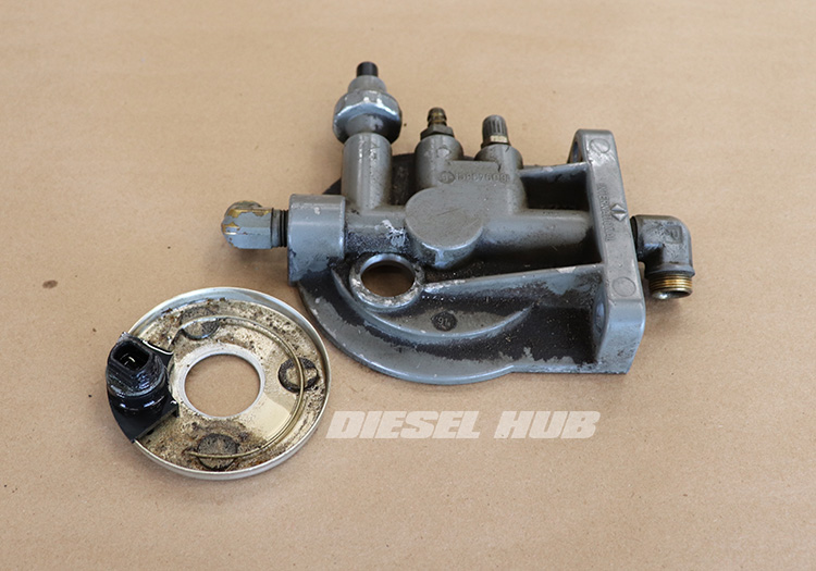
At room temperature, for example, the thermistor will keep the circuit open and there will be no continuity between the connector terminal and the actual heating element. When placed in a freezer then tested, the circuit will be closed and there will be continuity between the connector terminal and the heating element. For the heater to operate, the fuel temperature must be below the switching threshold of the thermistor. For this reason, this device is self-regulating and functions independent of ambient temperature; it is only when the fuel temperature drops below the switching threshold that current flows through the heating element. The heating element is ultimately grounded through the filter mount, which is grounded to the engine.
The exact temperature at which the resistance across the thermistor drops enough to allow significant current flow through the heating element is not advertised or referenced in Ford's service material. However, we do know that the fuel heater is intended to operate at and below freezing. The operation of the fuel heater will also change with age and use, so this temperature may not remain constant through the lifespan of the device.
Is The Fuel Heater Needed?
Every 7.3L IDI powered vehicle on the road is 30+ years old. We can safely assume that most of these vehicles are not in primary service under Arctic conditions. That being said, if you regularly drive your vehicle in sub-zero conditions you may be interested in preserving the fuel heater because it makes practical sense. For the rest of us, it is debatable as to whether or not this device is necessary, even when temperatures dip below freezing.
Appropriate fuel treatments are a cost effective, efficient method of preventing fuel waxing. Additionally, the actual performance and efficiency of the fuel heater are not well documented so we can not attest to how effective it is at "melting" waxed fuel. It also should not be able to prevent fuel waxing (in most instances) because fuel waxing begins in the tank. If the fuel pump cannot deliver fuel to the filter housing because it has crystallized, then heating fuel in the filter is a moot point.
Delete Advantages
There are no advantages to deleting the fuel heater unless it develops a leak. The pass-through connector of the heater is sealed to the filter mount with one or more o-rings. Newer style heaters seal with a single o-ring while the older units were sealed with two o-rings. These seals can become the source of a rather abrupt and significant fuel leak, or a slow leak that goes unnoticed over thousands of miles. Either way, fuel will pool in the engine valley and make a royal mess in the engine compartment. If the leak is severe enough, fuel pressure may drop and the engine may stall. Replacing the o-ring(s), which are rather inexpensive, is a simple fix. For additional information on replacing them, see 7.3 IDI fuel heater o-ring replacement.
Another failure point is in the bond between the thermistor, terminal, and the plastic connector housing. It is not uncommon for fuel to begin leaking through the connector. In this instance, there is no repair option other than replacing the heating element.
In either of these two cases, 7.3 IDI owners may choose to permanently delete the fuel heater and eliminate the potential for future leaks. This is really the only advantage to deleting the fuel heater - eliminating the potential for future leaks from a component that is unlikely providing any benefit. The Dieselply fuel heater delete accomplishes this by plugging the connector pass-through hole in the filter housing. The procedures below assume that this kit is being used. For convenience, printed versions of these instructions are included with each delete kit.

Continuous Vent Delete
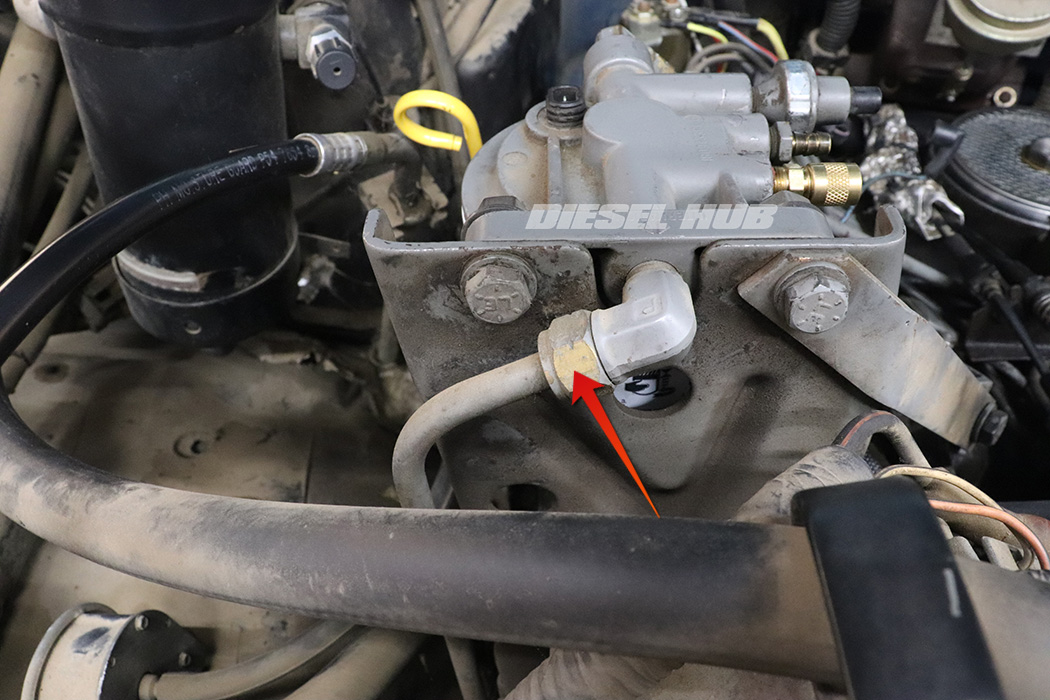
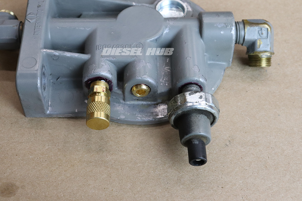
The continuous vent, also referred to as the fuel return orifice and check valve (or ball), is mounted between the fuel restriction sensor and the air bleed valve (also fuel test fitting). It consists of a barbed fitting with a small orifice, a spring, and a check ball. It is connected to the fuel return system by a section of hose. It is a known weakness in the fuel system that can allow air intrusion from the return system and/or can siphon fuel from the filter when the vehicle is off.
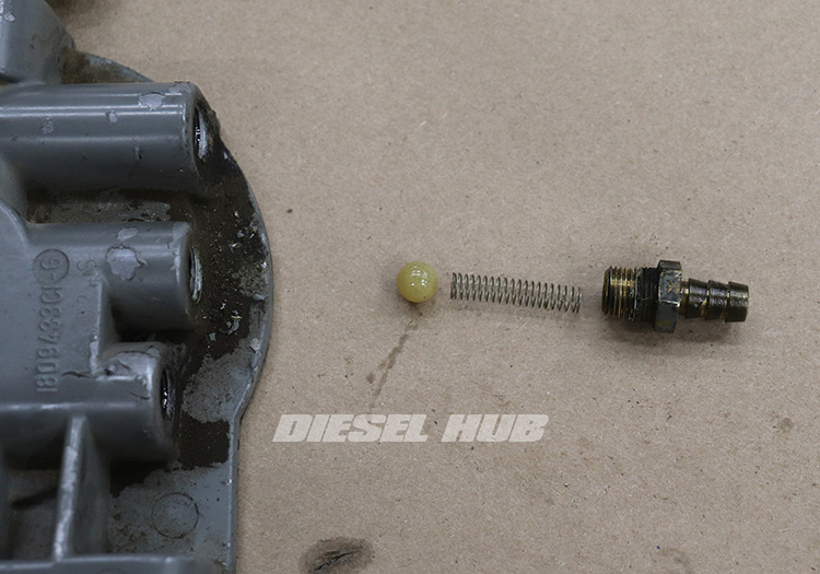
It was abandoned long ago in a TSB that predates the digital age. There is nothing to lose and everything to gain in deleting the continuous vent. In many instances, the check ball has dissolved and is missing when the barb fitting is removed. The kit used herein deletes both the fuel heater and the continuous vent.
How to Install a Fuel Heater Delete
Click any thumbnail to view fullsize, detailed image
- Disconnect both negative battery cables.
- Remove the fuel filter.
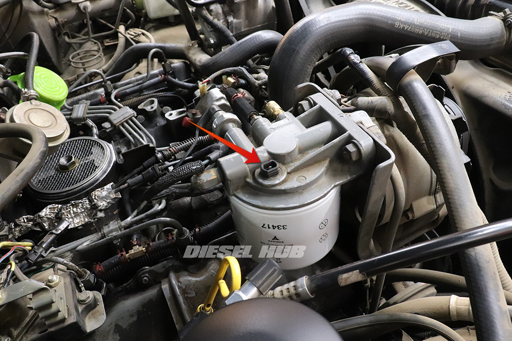
- Remove the fuel heater connector. It's a peculiar single terminal, sealed connector that often becomes brittle and stubborn. Working the perimeter with a flat head screwdriver generally helps dislodge it from the pass-through portion of the heater assembly.
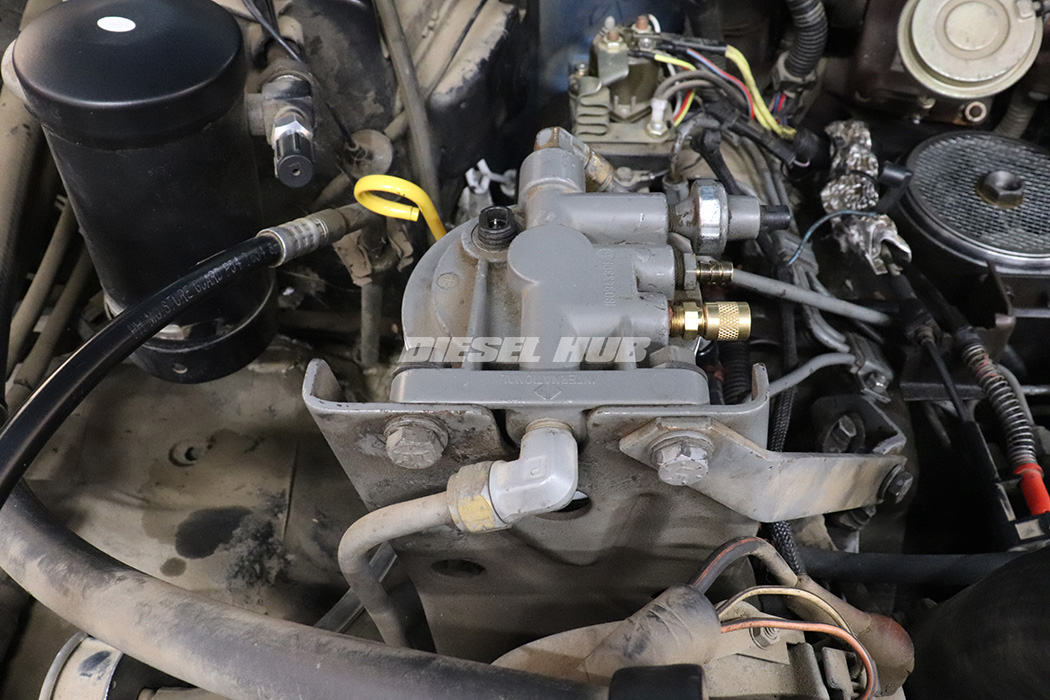
- Disconnect the fuel restriction sensor on the driver side of the filter base.
- Disconnect the fuel hose next to the test port/air bleed valve on the driver side of the filter base.
- Disconnect the fuel inlet line from the front of the filter base with a 3/4 inch flare nut wrench (connects fuel pump to filter base).
- Gently position the line off the fitting and plug it with a vacuum cap to prevent contamination.

- Disconnect the fuel outlet line from the rear of the filter base with a 5/8 inch flare nut wrench (connects filter base to injection pump).
- Gently position the line off the fitting and plug it with a vacuum cap to prevent contamination. This line carries filtered fuel and therefore there is no further line of defense if debris gets in this line - it will go to the injection pump.

- Remove the filter base mounting bolts with a 9/16 inch socket and wrench combination.

- Flip the filter base upside down and reinstall the mounting bolts hand tight.
- Break loose and remove the threaded filter adapter with a 1-1/4 socket or box end wrench.
- Break loose the fuel restriction sensor with a 1-1/16 inch socket or wrench.
- Break loose the barbed fitting with a 1/2 inch socket or wrench.
- Break loose the fuel bleed/pressure test fitting with a 7/16 inch socket or wrench.

- Remove the filter base from the bracket once more and set it on a workbench.
- Remove the fuel restriction sensor and air bleed/pressure test fitting.
- Remove the fuel heater element by pushing the connector through the filter base.

- Loosen the barbed fitting and slowly pull it from the housing.
- There should be a check ball and a spring behind the fitting. It is common for the check ball to disintegrate and be missing.
- In addition to deleting the fuel heater, the instructions below will cover how to delete the continuous vent. Note that this is optional and the check ball can be reinstalled if desired.

- Thoroughly clean the filter base and remove any grime to prevent contamination.
- The hole where the heater connector passes through the housing must be clean and free of debris before installing the delete plug.
- Apply a light coating of Loctite 680 retaining compound around the delete plug.

- Set the delete plug into place and align it so that it will drive in straight.

- Drive the plug into the opening using a hammer and an appropriately sized socket that fits on the rim of the plug, not inside it.
- Sockets vary in wall thickness and therefore actual outside diameter, so there may be some variance between tool brands; a 9/16 inch deep socket is used here.
- An arbor press may also be used, if available.

- It is not necessary that the delete plug is driven flush with the filter base, but it should end up fairly close.
- You should be able to feel when it has seated itself. It should not take an extremely hard blow to seat it.

- Flip the filter base over and clean up any residual retaining compound around the plug.
- The retaining compound reaches full cure strength in 24 hours.

- Apply Loctite 545 thread sealant to the small tapered plug.
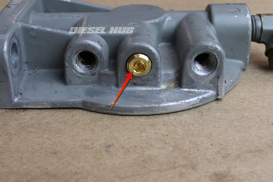
- Install the plug into the center port between the bleed valve and restriction sensor where the barb fitting/check ball were previously found.
- Tighten the plug snuggly but do not overtighten - the threads are tapered and over-tightening can result in cracking the housing.
- Reinstall the fuel restriction sensor and bleed valve.
- Both are tapered threads, do not overtighten.
- Loctite 545 is recommended on both to ensure a positive seal; a PTFE sealant can also be used, but do not substitute with Teflon tape.

- Apply high strength thread-locker to the brass filter adapter threads.
- Reinstall the brass filter adapter and torque to 50 ft-lbs. It may be necessary to secure the filter base on its mount to torque the adapter.
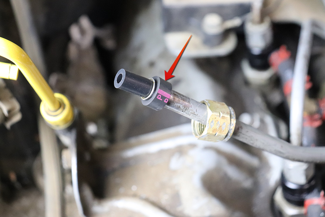
- Remove the old compression sleeves from the filter inlet and outlet fittings without dropping any pieces into the fuel line.
- Liberally coat the interior and exterior of the new compression sleeves in clean motor oil.
- Install the new compression sleeves.

- Position the filter base in place and start the threads on the inlet and outlet line fittings.
- Install the filter mounting bolts.
- Tighten all fittings and bolts.
- Reconnect the fuel restriction sensor connector.
- Install a new fuel filter.
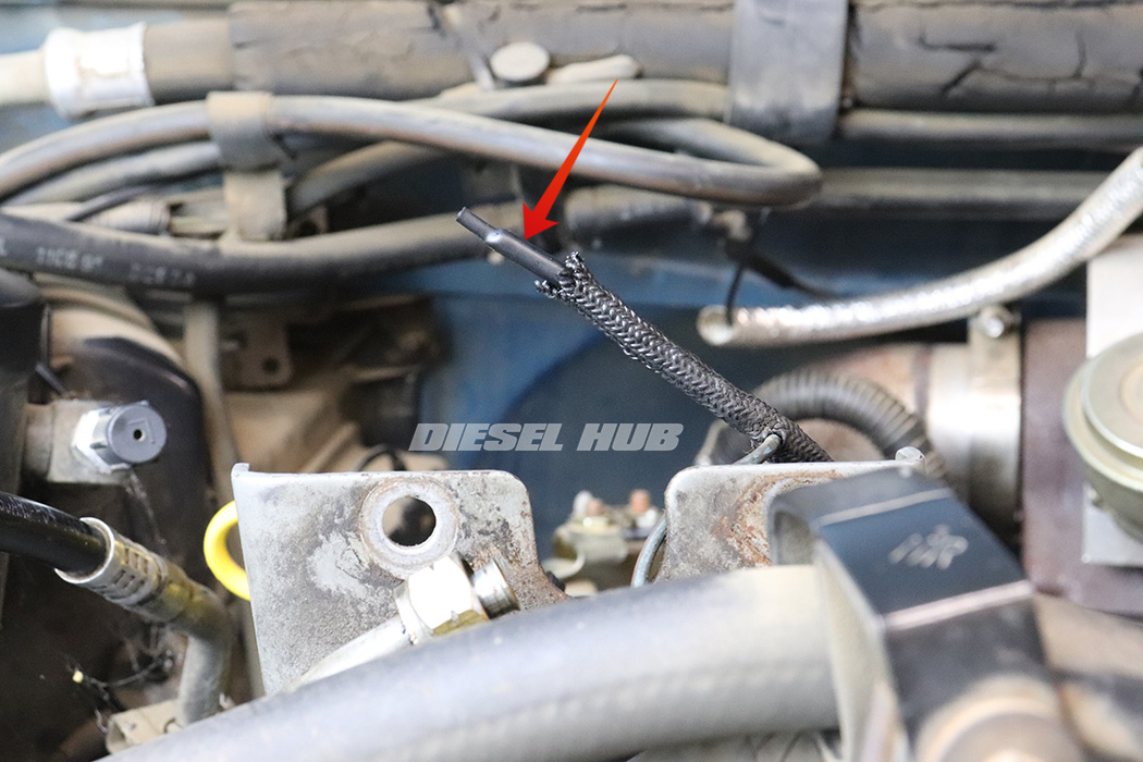
- Cut the connector from the wire for the fuel heater.
- Slide the supplied heat shrink cap over the wire, then apply heat to secure it over the wire.
- Secure the wire to the harness so that it is out of the way.
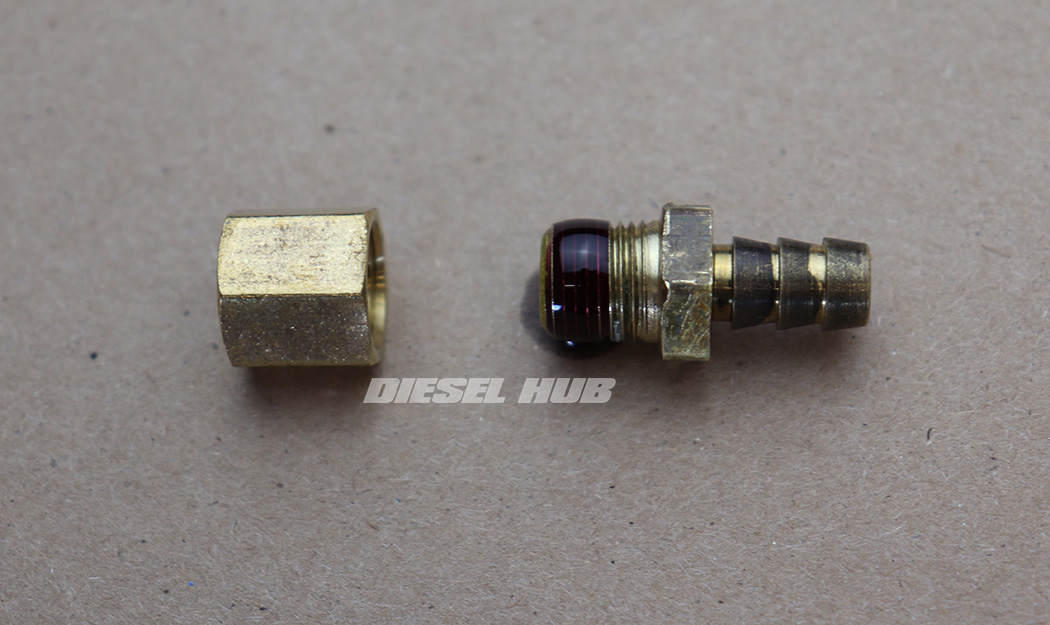
- Apply Loctite 545 to the barbed fitting removed from the filter base (previously with check ball behind it).
- Thread the supplied cap onto the threaded end of the barbed fitting and snug down with a wrench.
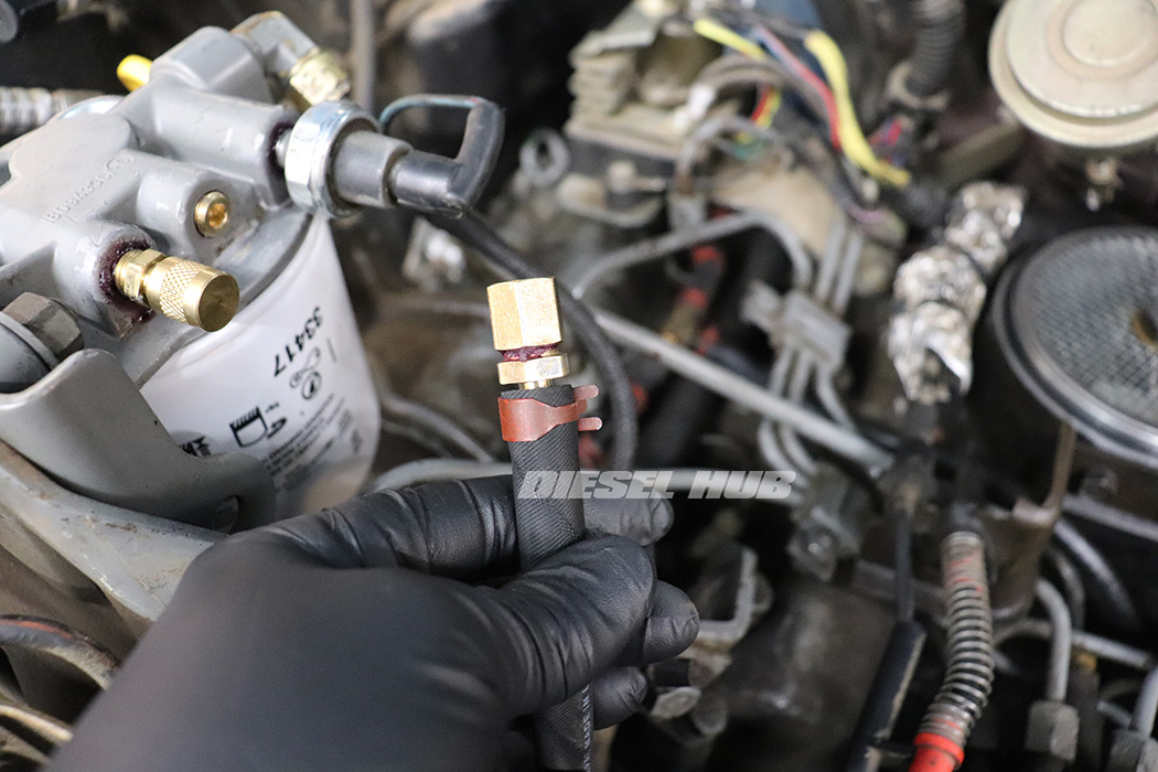
- Reinstall the barbed fitting (now capped off) into the return line hose and secure with the original hose clamp.
- Tuck the return line hose into a safe position and secure with a cable tie.
- Allow the retaining compound and thread sealant to cure for 24 hours.
- Start the engine and check for fuel leaks.

