1994 to 1997 model year 7.3 liter Power Stroke engines utilize a two stage mechanical fuel pump. This fuel pump is typically referred to as the lift pump and it provides low pressure fuel to each fuel injector through a network of galleries machined into the cylinder heads. Because of its HEUI injection system, the 7.3 Power Stroke does not have a traditional high pressure fuel pump (injection or injector pump). Instead, oil pressure acting on an intensifier piston in the cylinder head creates the final injection pressure.
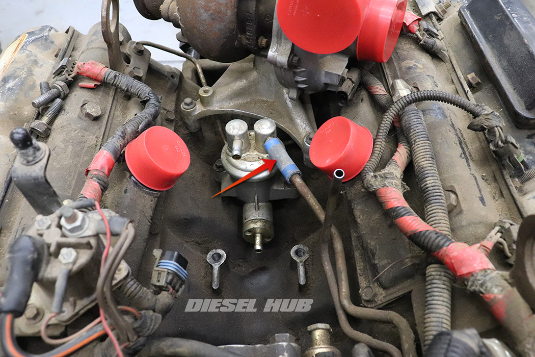
The fuel pump has two pumping stages - the low pressure stage is handled by the diaphragm in the upper section of the pump housing. A camshaft lobe acting on the pumping mechanism at the base of the pump moves the diaphragm up-and-down, creating suction on the tank side and pressure on the outlet side. At this point low pressure, unfiltered fuel travels from the fuel pump and into the fuel filter housing (fuel bowl) where it is forced through the filter and leaves the bottom port of the filter housing and into the piston stage of the fuel pump. Here, a piston in the lower section of the pump housing ramps up fuel pressure and distributes it to the fuel gallery in each cylinder head.

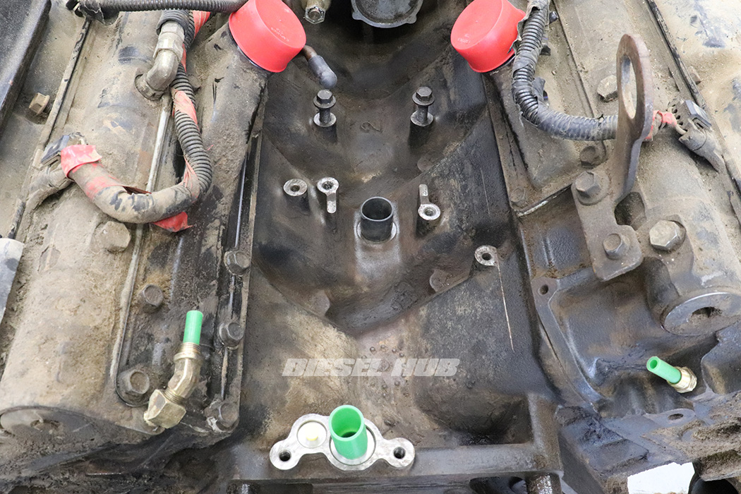
- Low pressure stage inlet, unfiltered fuel from the tank (diaphragm stage inlet)
- Low pressure stage outlet, unfiltered fuel to the filter housing (diaphragm stage outlet)
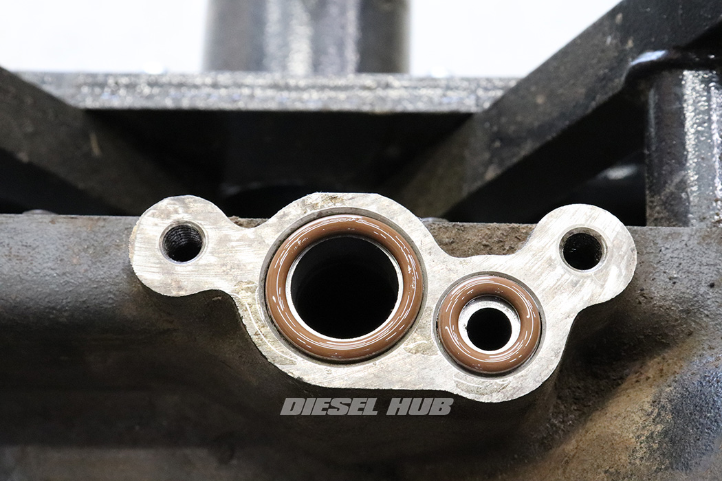
- High pressure stage inlet, filtered fuel from the filter housing (piston stage inlet); fuel is at low pressure entering the fuel pump at this stage
- High pressure stage outlet, filtered fuel distributed to each cylinder head circuit (piston stage outlet); fuel is at high pressure leaving the fuel pump
- Fuel tank return circuit (return to fuel tank)
- Fuel pump drive mechanism (camshaft lobe acts on the base of the mechanism)
Associated Parts
| Component | Part Number | Remarks |
|---|---|---|
| Fuel pump | Ford F6TZ-9350-A Carter M61067 |
[1] |
| Fuel pulse damper | Ford F6TZ-9N163-AA | [2] |
| Banjo bolt sealing washers | Ford F4TZ-9A375-A | |
| Return hoses | Ford F4TZ-9B273-A (passenger) | [3] |
| Ford F4TZ-9D308-A (driver) | ||
| Compression sleeve set | DP-1609K | [4] |
| Fuel bowl hose kit | DP-1637K | [5] |
| Turbocharger install kit | DP-1207K | [6] |
[1] - Carter is the original equipment fuel pump manufacturer
[2] - Only found on 1996 and 1997 model year engines with a California emissions package and all 1997 and 1998 Econoline Vans
[3] - Reuse if in good condition
[4] - Generally requires replacement when lines are disconnected, not necessary if recently replaced
[5] - Kit contains each of the hoses and clamps necessary to reinstall the filter housing
[6] -
Basic reinstall kit containing the bare-minimum assortment of parts that are not generally reusable
Fuel Pulse Damper
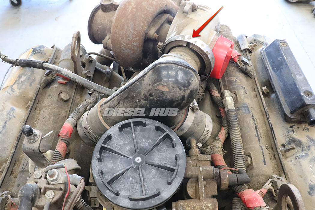
Some 1996 model and all 1997 model year F-Series engines with a California emissions package utilize a fuel pulse damper that is mounted at the high pressure outlet of the fuel pump. All engines in 1997 and 1998 Econoline vans are also equipped with this device. You might describe is as the black "flying saucer" mounted beneath the turbocharger.

Ford also refers to this component as an accumulator. Its purpose is to dampen pressure pulsations in the fuel system in the aforementioned applications because they utilize split-shot injectors. Because the fuel pump is mechanically driven off the camshaft pressure spikes and falls with the rotation of the engine - this apparatus smooths out the pulsations. Applicable vehicles should retain this device, but there are no inherent benefits in converting an engine with single shot injectors to a pulse dampened fuel system.
How to Replace the Fuel Pump on a 7.3 Power Stroke Diesel
Click any thumbnail to view fullsize, detailed image
- Disconnect both negative battery cables.
- Remove the intake hose from the air filter box to the turbocharger compressor inlet.
- Loosen the Marman clamp that secures the intake "Y" plenum to the turbocharger compressor outlet.
- Loosen all hose clamps for the rubber intake boots that distribute air from the "Y" plenum to the cylinder head plenums.
- Remove the intake "Y" plenum from the engine and plug all cylinder head/turbo openings.

- Drain the fuel bowl into a suitable container.
- Remove the flexible return lines from the fuel bowl pressure regulator fittings with a 9/16 inch wrench.
- Plug the return lines; fuel from these lines can be returned to the primary fuel circuit without being filtered, so it is crucial to protect against infiltration.

- Completely loosen all hose clamps that connect the fuel bowl to the fuel pump and the pressure regulator to the tank return hard-line.
- Remove the fuel filter housing.
- Slide the fuel pump inlet hose (driver side, upper port) over the rigid fuel line such that it is no longer connected to the fuel pump.
- Plug all inlet/outlet port fittings and lines with vacuum caps (or equivalent) to prevent debris infiltration.
- Remove the turbocharger.
- Carefully plug the turbocharger pedestal oil feed and drain ports to prevent debris infiltration.

- If applicable, remove the fuel pulse damper (accumulator) from the rear of the fuel pump with a 1-1/16 inch wrench.

- Clean out the engine valley, removing as much debris and fuel as possible.
- When the fuel pump is removed debris and fluids left in the valley will very easily fall into the opening and onto the adjacent camshaft lobe - the engine valley should be especially clean before the pump is physically removed.
- Completely loosen the fuel line connections at the rear of each cylinder head with a 9/16 inch wrench.
- Remove the banjo bolt at the rear of the fuel pump with a 1-1/4 socket or wrench.
- Remove the fuel pump outlet lines.
- When the banjo bolt is removed, fuel is going to flood the engine valley - let it drain and clean it once more before physically removing the fuel pump.
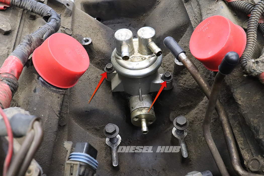
- Completely remove the (2) fuel pump mounting bolts with a 10 mm socket or wrench. It is best to alternate between the left and right mounting bolts since the fuel pump is likely to be under spring pressure.

- Pull the fuel pump straight upwards to remove. Twisting it while keeping tension upwards will help persuade the stiff o-ring out of the bore.
- Immediately plug the hole in the engine valley.
- If not previously able to, remove the outlet line assembly and plug both fittings at the rear of the cylinder head.
- Clean out the engine valley once more, preferably with a vacuum cleaner. There always seem to be debris built up around the base of the pump, especially if its been leaking.
- A perfectly clean engine valley makes it incredibly easy to detect leaks later on.
- As necessary, clean the fuel fittings at the rear of each cylinder head. If the compression sleeves are old, they are likely caked with fuel and dirt buildup.

- Remove the old banjo bolt seals.
- There is a large washer-type seal on either side of the opening where the fuel pump attaches..
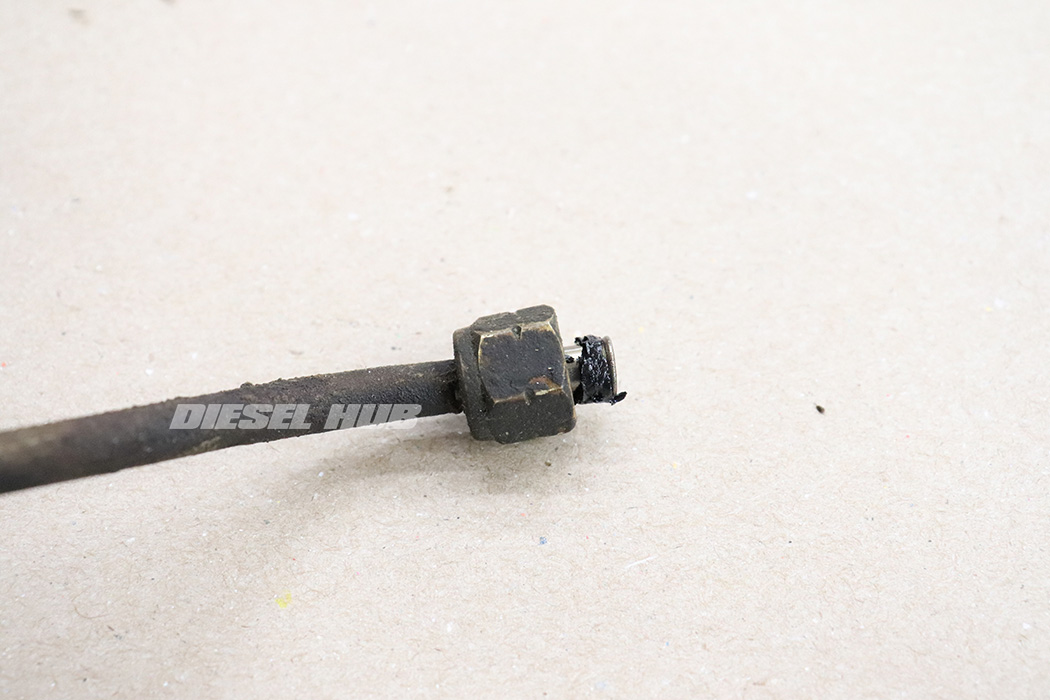
- Remove the compression sleeves without letting bits fall into the fuel line.
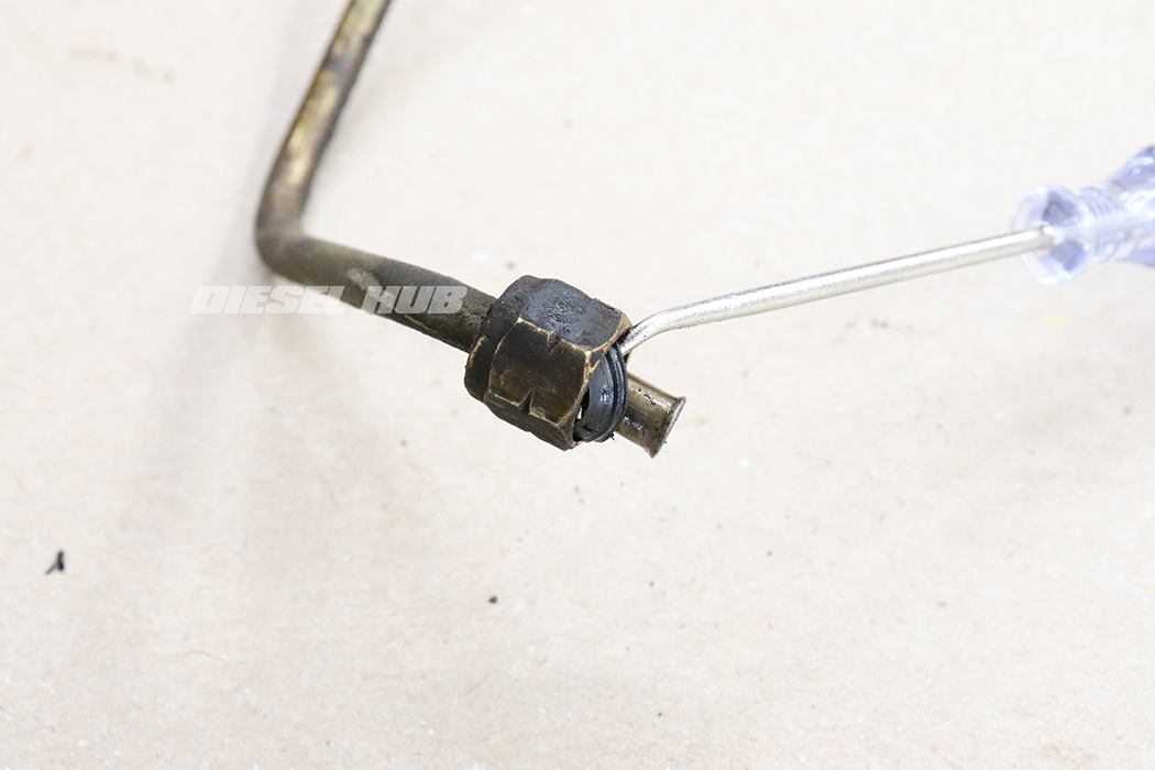
- Inspect the base of the threads on the female fuel line fittings, as the compression sleeves age they get hard and tend to hide inside the fitting.
- Verify that there are no compression sleeve remnants on either outlet fitting.
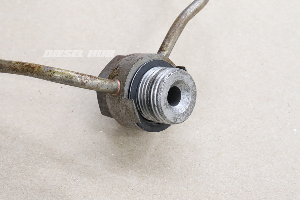
- Thoroughly clean the the fuel lines, particularly the sealing areas, and blow out the lines with compressed air. To ensure a positive seal, the flared portion of the fuel lines and the threaded fittings must be reasonably clean.

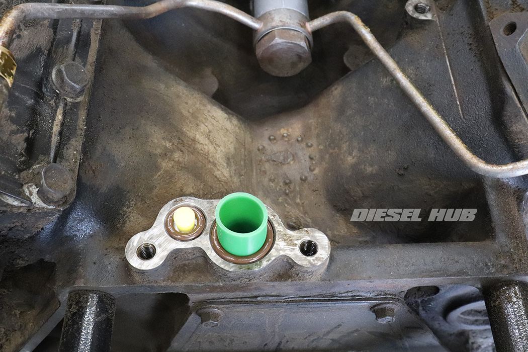
- Lubricate the fuel pump o-ring with clean motor oil and install it onto the fuel pump shaft landing.
- Note - fuel pump o-ring may already be installed, coat thoroughly with clean motor oil.
- Optional - apply a small amount of assembly lube to the surface of the fuel pump plunger (contact surface between the camshaft lobe and plunger).

- Install the fuel pump in reverse order, twisting side-to-side as pushing downwards.
- When you reach the point where the fuel pump can only be inserted further by overcoming spring pressure, install the fuel pump mounting bolts finger tight.
- Tighten the fuel pump mounting bolts in an alternating fashion while keeping the gap between the left and right sides relatively even. If the fuel pump is not tightened down evenly the housing will crack.
- Once the fuel pump is mounted flush to the valley, torque bolts to 18 ft-lbs.

- Install the hose connection for the fuel pump inlet (driver side, upper port) and secure the clamps.
- Thoroughly coat each compression sleeve in clean motor oil and install them over the flared portion of both fuel lines (as pictured).
- Install a sealing washer over the banjo bolt.
- Insert the banjo bolt into the fuel line opening, then install the second sealing washer.
- There should be a single sealing washer on either side of the fuel line opening.

- Reinstall the rigid fuel lines at the fuel pump and the cylinder heads.
- Note the "tangs" at the banjo bolt that must line up with slots in the fuel pump housing for the system to seal correctly.
- Torque the banjo bolt to 37 ft-lbs.
- Tighten the cylinder head fittings snugly. Once the gap between the nut and the adjacent fitting is closed, the fitting is properly secured.
- Replace the turbocharger pedestal oil feed and return o-rings.
- Reinstall the turbocharger.
- Reinstall the fuel filter housing.
- Prime the fuel system.
- Start the engine and test for leaks.

