The 7.3 Power Stroke utilizes a valve cover gasket with a pass-thru electrical connector. It serves to connect the engine wiring harness to the under valve cover harness (UVCH), which supplies power to the fuel injectors and glow plugs. The exposure to oil and heat contribute to accelerated degradation of these components. When the pass-thru connector or any part of the UVCH experiences high resistance due to a poor connection, intermittent fuel injector problems can surface in the form of rough running or misfire conditions.
There are two types of valve cover gaskets associated with the 7.3 Power Stroke engine. 1994 to 1997 engines have the early style gasket, which incorporates two (5) pin pass-thru connectors. Late style gaskets, 1998 to 2003 model year engines, incorporate a single (9) pin pass-thru connector into each valve cover gasket. In the early style, each corresponding connector at the wiring harness services (2) glow plugs and (2) fuel injectors in each bank. On the later style, each connector services one entire bank of (4) glow plugs and (4) fuel injectors.
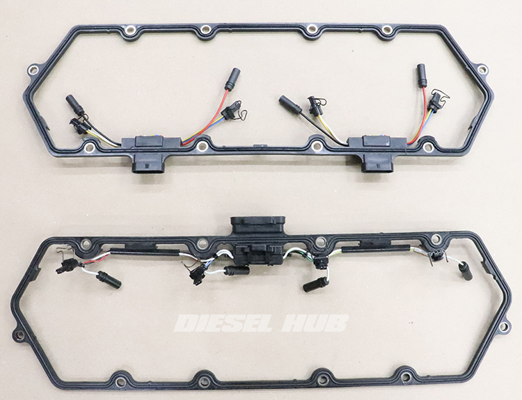
1994 to 1997 model year engines utilize dual 5 pin through valve cover connectors (top)
1999 - 2003 model year engines utilize a single 9 pin through valve cover connector (bottom)
Diagnostics
There's a few different methods for verifying the condition of the valve cover gasket pass-thru connector and under valve cover harness. In any instance, it requires only a digital multimeter to check resistance across various points in the circuit. The more thorough method of doing this requires removing the valve cover gasket and UVCH from the engine and measuring the resistance across each terminal in the valve cover gasket and the corresponding terminal at the injector connectors. High resistance across any of these circuits should prompt disassembly of the UVCH from the valve cover gasket, then additional measurements are taken to isolate which connection or connector that the issue is specific to. In all likelihood, the valve cover gasket and corresponding UVCH should be replaced together.
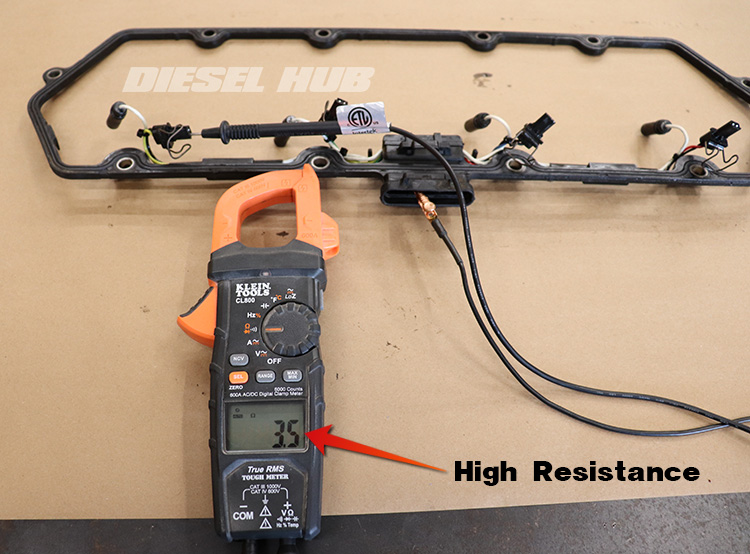
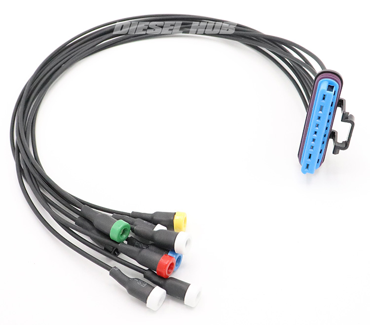
A more efficient method that does not require any disassembly of the engine is to use a breakout tool to measure resistance across each injector. The valve cover connector on the engine side of the harness is unplugged and the breakout tool is installed into the valve cover connector. Next, the resistance across each fuel injector solenoid is measured through the breakout tool. If any injector reads out of specification - more than 3.6 Ohms - the valve cover gaskets are removed to perform the aforementioned resistance measurements between the valve cover gasket thru-connector and the individual injector connectors.
Note that this breakout tool is also useful in testing glow plugs without removing the valve covers but it cannot always catch intermittent issues, nor can it verify the condition of the valve cover gasket connector on the engine side. It's still a very useful tool for 7.3 liter Power Stroke owners, and we offer a premium USA made equivalent of the Ford/Rotunda tool (figure 3, below) at a fraction of their price.
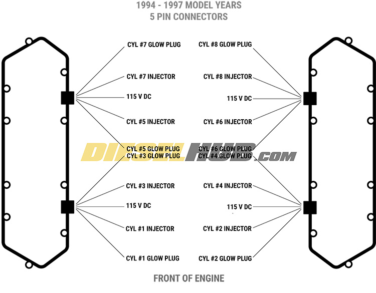
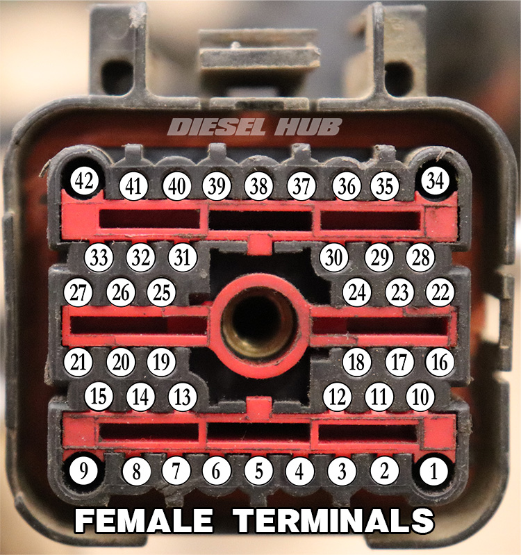
If the fault were in the engine wiring harness or one of its associated connectors, the diagnostic sequence remains the same - measure resistance across individual circuits until the problem is found. The pinout diagrams below (figures 4 - 6, table 1) will aid in determining the landing points of various connectors related to the fuel injection system.
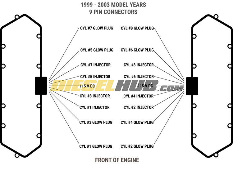
| Pin # [1] | Circuit Description |
|---|---|
| 2 | Fuel injector 1 |
| 3 | Fuel injector 2 |
| 4 | Fuel injector 7 |
| 5 | Fuel injector 3 |
| 6 | Fuel injector 4 |
| 7 | Fuel injector 5 |
| 8 | Fuel injector 6 |
| 10 | Fuel injector 8 |
| 11 | Shared 115 V DC+ to injectors 2, 4, 6, 8 (driver side bank) |
| 12 | Shared 115 V DC+ to injectors 1, 3, 5, 7 (passenger side bank) |
[1] - Circuits that are not associated with the fuel injection system have been omitted from this chart
With these pinout diagrams, you can measure the individual injector circuits between the large 42 way connector and each fuel injector, UVCH connector, or valve cover gasket connector. Bear in mind that the IDM provides a shared 115 volt DC positive circuit to each valve cover gasket connector. To fire a fuel injector, the IDM grounds the corresponding circuit that is unique to each injector. The 42 way connector is the same for all model years, but its location is different. On OBS trucks it is located next to the fuse box located in the engine compartment. On Super Duty trucks, it is mounted to a bracket on the driver side valve cover.
Associated Parts
| Component(s) | Part Number(s) | Remarks | |
|---|---|---|---|
| Valve cover gasket connector | 1994-1997 | Alliant AP0015 | [2] |
| 1998-2003 | Dieselply DP-152301 | [3] | |
| Valve cover gasket | 1994-1997 | Ford F4TZ-6584-A | [4] |
| 1998-2003 | Ford F81Z-6584-AA | ||
| Under valve cover harness | 1994-1997 | Ford F4TZ9-D930-K | --- |
| 1998 - 2003 | Ford F81Z-9D930-AB | ||
[2] - (5) pin connector, 1994 to 1998 engines, (2) required per cylinder head
[3] - (9) pin connector, 1999 to 2003 engines, (1) required per cylinder head
[4] - Recommend replacing valve cover gaskets and connectors (engine side) simultaneously to ensure greatest cohesion
How to Replace the Valve Cover Gasket & UVCH
Click any thumbnail to view fullsize, detailed image

- Disconnect both negative battery cables.
- Remove the applicable valve cover; if desired, see 7.3 Power Stroke valve cover removal for addition guidance.

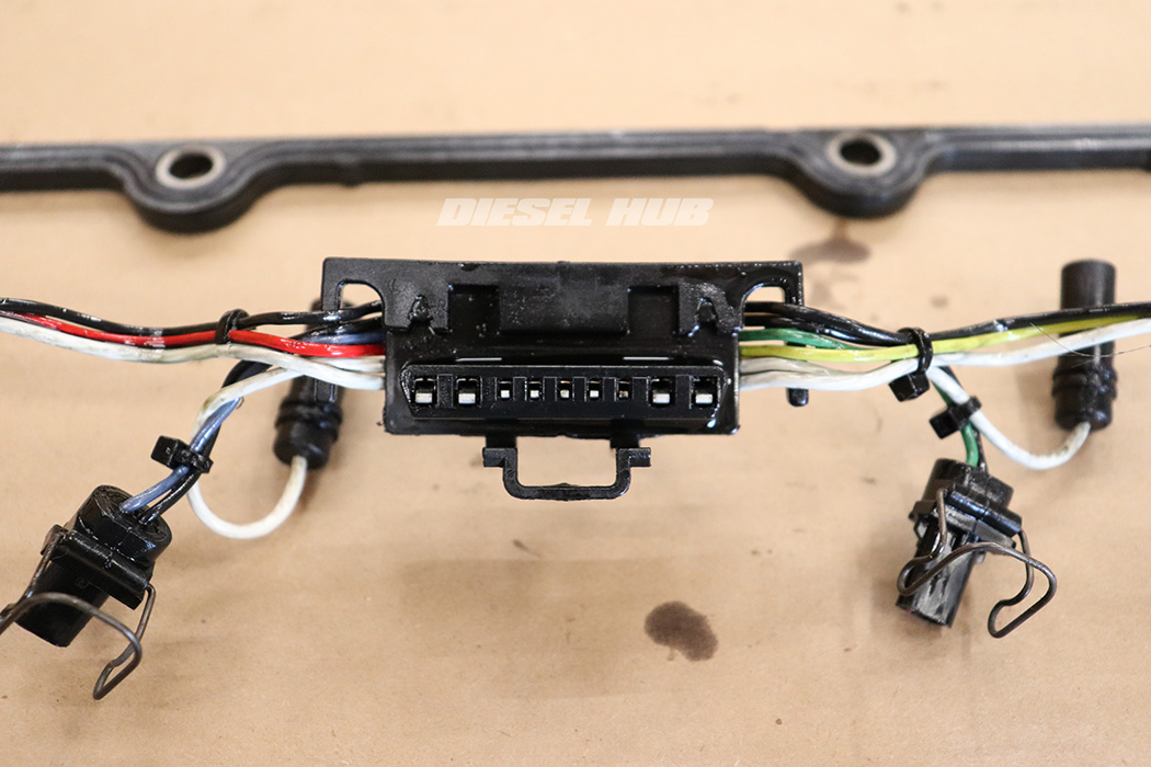
- Disconnect the valve cover gasket connector(s) by depressing the locking tab and pulling away from the cylinder head and towards the engine valley.
- Note that 1994 to 1997 engines have (2) connectors per valve cover and 1998 to 2003 engines have a single connector at each valve cover - late style valve cover gasket connector shown.

- For each fuel injector, disengage the locking tang then carefully pull the connector out of the injector solenoid.
- Remove the electrical connector from each glow plug by pulling it upwards.

- Remove the valve cover gasket from the engine and set it on a clean work bench.

- Locate the series of locking tabs that secures the UVCH harness(es) to the valve cover gasket.
- To remove a UVCH, relieve the locking tab and separate it from the valve cover gasket.
- The UVCH can also be separated from the valve cover gasket by relieving the locking tab and separating the two connectors.
- All components are reinstalled in reverse order as necessary. If you are replacing the valve cover gasket and UVCH, there is obviously no need to disassemble any of the old parts.
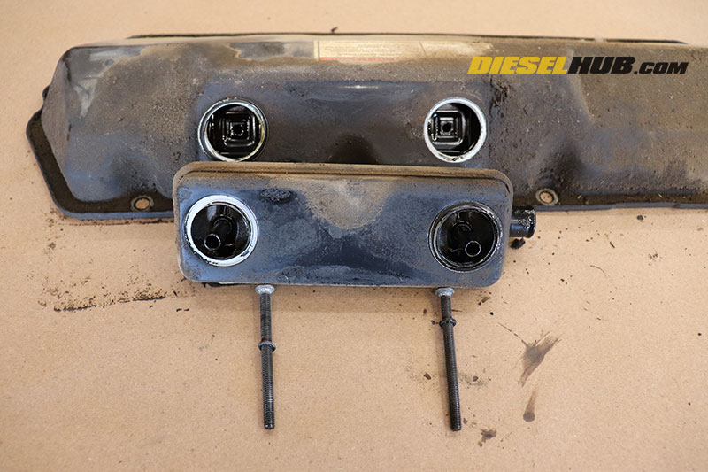
- Now is a convenient time to clean and reseal the CCV.
- This is especially important for 1998 and newer engines as the 9 way valve cover gasket connector sits right next to the unit. Compromised seals or an excessively dirty vent can result in oil mist escaping and infiltrating the connector; the combination of heat and oil exposure reduces its life and attacks the plastic components.

