Applicable Models:
1994.5 - 1997 Ford F-250, F-350, F-Super Duty
1999 - 2003 Ford F-250, F-350, F-450, F-550 Super Duty
2000 - 2003 Ford Excursion
1995 - 1999 Ford Econoline E-350
2000 - 2003 Ford F-650, F-750
2000 - 2003 Econoline E-350, E-450, E-550
Applicable Engine(s):
7.3 liter Power Stroke V-8 (7.3 DIT)
The fuel injectors in the 7.3 Power Stroke engine are actuated electronically via the injector driver module (IDM). The IDM circuit connects to the main engine wiring harness at the large square connector mounted atop the driver side valve cover on 1999 and newer engines and located near the fuse box on on earlier models. From there, wiring harness connectors attach to a pass-thru connector integrated into the valve cover gasket, which is connected to another set of harnesses beneath the valve cover. This harness is called the under valve cover harness, or UVCH, and it has connectors for each glow plug and fuel injector.
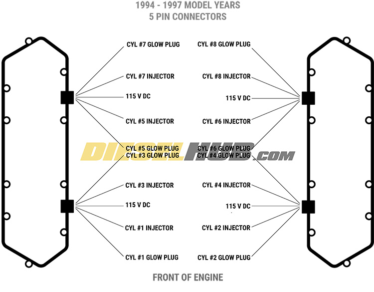
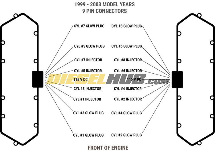
On 1994 to 1997 engines, two (5) pin wiring harness connectors attach to each valve cover gasket. For 1998 and newer engines, a single (9) pin wiring harness connector attaches to each valve cover gasket. These are referred to as the valve cover gasket connectors. They are subjected to significant heat, vibration, and even oil infiltration. The combination of heat and oil accelerate degradation of the connector and wire insulation. If this connection becomes compromised, it is common for engines to run rough, misfire, experience a hard start/long crank condition, or in severe cases the engine will not start and run.
Diagnostics
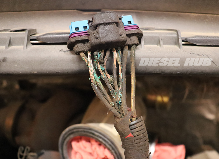
The valve cover gasket connector and UVCH are obvious prospects in the event of an injector misfire, particularly if the issues are intermittent. If an entire bank of cylinders is experiencing issues, this is even more telling of a valve cover gasket connector related concern. In the early stages of a connector failure, problems will usually exhibit intermittent behavior and may be difficult to trace. Other times, the connector is so obviously damaged that a diagnostic is purely visual (figure 1, above) - if the wires are frayed or the connector appears damaged, it needs to be replaced regardless.
Adjusting the connector, whether that means pushing into the valve cover pass-thru connector or prying the locking tab with a flat blade screwdriver to change the terminal contact angle, is an early detection method. If the problem goes away or the symptoms change after the adjustment, it is probable that this connection is poor. An injector buzz test can help determine which injectors are receiving a weak or interrupted signal. This is particularly useful on earlier engines, which have a total of four valve cover gasket connectors.
Pinout Diagrams
The pinout diagrams below (figures 4 - 6, table 1) will aid in determining the landing points of various connectors related to the fuel injection system. Measuring resistance through the various circuits is generally productive in identifying the source of a problem related to the UVCH and valve cover gasket connectors.
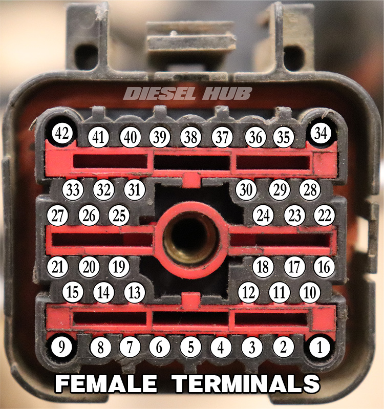
| Pin # [1] | Circuit Description |
|---|---|
| 2 | Fuel injector 1 |
| 3 | Fuel injector 2 |
| 4 | Fuel injector 7 |
| 5 | Fuel injector 3 |
| 6 | Fuel injector 4 |
| 7 | Fuel injector 5 |
| 8 | Fuel injector 6 |
| 10 | Fuel injector 8 |
| 11 | Shared 115 V DC+ to injectors 2, 4, 6, 8 (driver side bank) |
| 12 | Shared 115 V DC+ to injectors 1, 3, 5, 7 (passenger side bank) |
[1] - Circuits that are not associated with the fuel injector system have been omitted from this chart
With these pinout diagrams, you can measure the individual injector circuits between the large 42 way connector and each fuel injector, UVCH connector, or valve cover gasket connector. Bear in mind that the IDM provides a shared 115 volt DC positive circuit to each valve cover gasket connector. To fire a fuel injector, the IDM grounds the corresponding circuit that is unique to each injector. The 42 way connector is the same for all model years, but its location is different. On OBS trucks it is located next to the fuse box located in the engine compartment. On Super Duty trucks, it is mounted to a bracket on the driver side valve cover.
Associated Parts
| Component(s) | Part Number(s) | Remarks | |
|---|---|---|---|
| Valve cover gasket connector | 1994-1997 | Alliant AP0015 | [1] |
| 1998-2003 | Dieselply DP-152301 | [2] | |
| Valve cover gasket | 1994-1997 | Ford F4TZ-6584-A | [3] |
| 1998-2003 | Ford F81Z-6584-AA | ||
| Under valve cover harness | 1994-1997 | Ford F4TZ9-D930-K | [4] |
| 1998 - 2003 | Ford F81Z-9D930-AB | ||
[1] - (5) pin connector, 1994 to 1998 engines, (2) required per cylinder head
[2] - (9) pin connector, 1999 to 2003 engines, (1) required per cylinder head
[3] - Recommend replacing valve cover gaskets and connector simultaneously to ensure greatest cohesion
[4] - Can be reused if harness and connectors tested good
Connector Options
The domestic market is flooded with cheap, low quality valve cover gasket connectors. They are often sold as a kit that includes the valve cover gaskets, under valve cover harnesses, and the valve cover gasket connectors - often at a very low price that American manufacturers cannot begin to approach. These are low quality parts mass produced in China that have thin-walled terminals, weak wire insulation, poor fitment, and ultimately a part that is more vulnerable to the harsh environment within the engine compartment. This is an absolute, prime example of getting what you pay for.
I highly recommend replacement connectors from Dieselply or Alliant Power, both of which are American made products and the connectors are assembled from the OEM parts. In particular, the Dieselply connectors utilize a high grade wire with exceptional heat and oil resistance. Choosing one of these USA made options supports domestic manufacturing, suppresses counterfeit operations, and ensures your engine is getting OEM quality parts.
Soldering vs Splicing
Installing connector pigtails can be done with butt splices or by soldering individual wires. Each process has its respective advantages and disadvantages, but soldering always results in a more coherent bond and reliable signal; therefore, I always recommend it for sensitive circuits like these. When done correctly, you will be left with a permanent bond between two wires. Once heat shrink tubing is secured over the splice, the overall diameter of the joint will be significantly smaller than if butt splices were used. This is beneficial in fitting the wires back into the wiring harness, especially on the later style connectors that have nine wires to splice at each connector.
Shielded Circuits
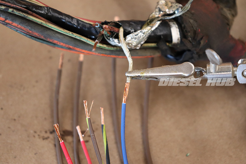
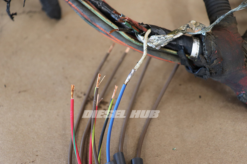
When unraveling the engine wiring harness, you'll note that the fuel injector wires are shielded - wrapped in a metallic foil that also carries a bare ground wire. This is to prevent possible interference between the high voltage injector circuits and the low voltage signal circuits packaged in the same wire covering. Once the valve cover gasket connector has been replaced, it is necessary to put the foil and ground wire back in place to avoid possible signal interference. The foil is quite thick and resilient, but care should be taken to unwind it from the wires without damaging it.
How to Replace a Valve Cover Harness Connector
The following procedures are based on later model engines that utilize a 9 way connector at each cylinder head. The steps are actually quite simpler on the earlier 5 way connectors because the engine compartment is not as busy and there are less components to contend with. The premise is exactly the same as the steps outlined below regardless of the connector style. I also find that it is much easier to remove the entire engine wiring harness than to attempt the repairs from atop the engine - it's much more intuitive to remove and install than you might think. If you decide to go this route, label any connectors that may not be obvious to you.
Click any thumbnail to view fullsize, detailed image

- Disconnect both negative battery cables.
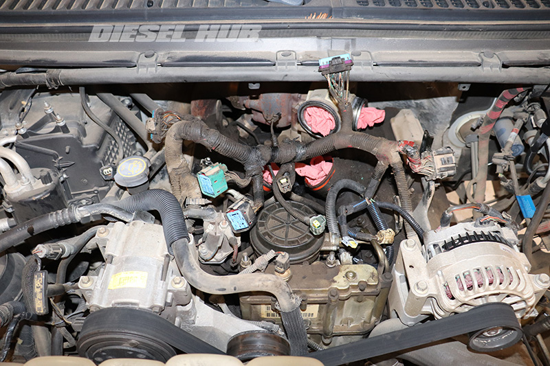
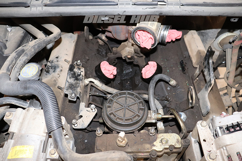
- Removing the following, as applicable to the engine model year: engine access cover, intake tubing to the turbocharger, intercooler tubes (hot and cold side), and the intake air distribution plenum on the turbocharger compressor outlet.
- Cover the turbo compressor inlet/outlet and the intake plenum inlets to prevent foreign debris from entering these openings.
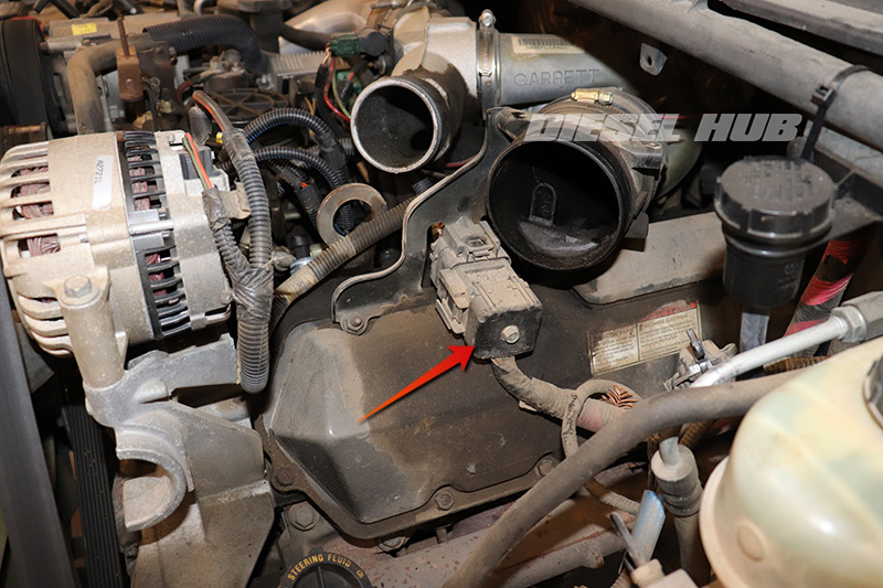
- Locate the large, square main engine wiring harness connector.
- On 1994 to 1997 engines, this connector is mounted to the left of the fuse box located on the driver side of the engine compartment.
- On 1998 to 2003 engines, this connector is mounted to a bracket on the driver side valve cover (pictured).
- Completely unthread the retaining bolt that passes through the center of the connector with a 10 mm socket, then release the retaining clip and separate the connector halves.

- Disconnect each valve cover gasket connector from both banks of cylinders by depressing the locking tab and pulling away from the cylinder head.
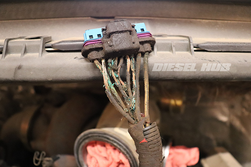
- This is a prime example of a severely damaged connector, no diagnostics necessary. Believe it or not, this engine ran - it was a hard start/long crank condition that prompted the owner to bring this in. This connector was original to the 22 year old, 280,000 mile engine.
- Noting that repairs can be performed without removing the wiring harness, begin to label components as necessary if you plan on removing the harness and performing the repairs on a workbench.
- Removing the serpentine belt from the alternator pulley will create clearance for some of the more difficult-to-reach connectors at the front of the engine.
- For the most part, removing the wiring harness is relatively intuitive; start on one side and work your way to the other. You may find the the EBPV tube and/or AC compressor bracket need to be removed to fish the camshaft position sensor connector upwards and into the engine valley.
- Once the harness is removed, set it on a clean workspace.
- On a side note, now is a convenient time to clean oil and gunk that has collected in the engine valley.

- Begin by removing the first section of wire loom closest to each connector.
- The wire loom and tape are likely to be quite brittle and you may need to cut through some of the material with a knife. Be cautious not to unintentionally knick any of the wires that are being replaced.

- Continue to remove the wiring coverings until you've found good wire in adequate condition.
- If the wire insulation is frayed or damaged, keep removing loom until a good section is found.

- Note that the injector wires are shielded and need to remain that way because they carry a high DC voltage. The shielding material should be meticulously unraveled and peeled back in a manner that it can be reinstalled over the wires later.

- Plan the cut and splice. I recommend cutting the engine wires and glow plug wires at separate lengths to reduce bulk. (9) splices with (9) sections of heat shrink tubing stacked on top one another creates a very bulky result that will be difficult to re-cover and integrate back into the harness.
- Verify that you can very clearly distinguish between each wire color in the injector circuit. If the wire insulation is faded and the colors are difficult to distinguish, label each wire on either side of where you plant to cut. If the cut is made in-between two labels, you will always be able to match them.
Note - the wires for the glow plug circuit are brown and use a much larger wire gauge than the injector circuits. For engines with California emissions that utilize a glow plug control module, the glow plug wires should be labeled and matched because the controller has the ability to gather information from each individual circuit. For engines with a Federal emissions package (glow plug relay only, no control module) there is no need to match glow plug wires, each bank gets bundled together in the harness.

- Cut the old connector from the wiring harness.
- As previously discussed, the glow plug wires have been cut at a longer length than the injector wires so that the completed splices can be tucked into the loom for a clean finish.
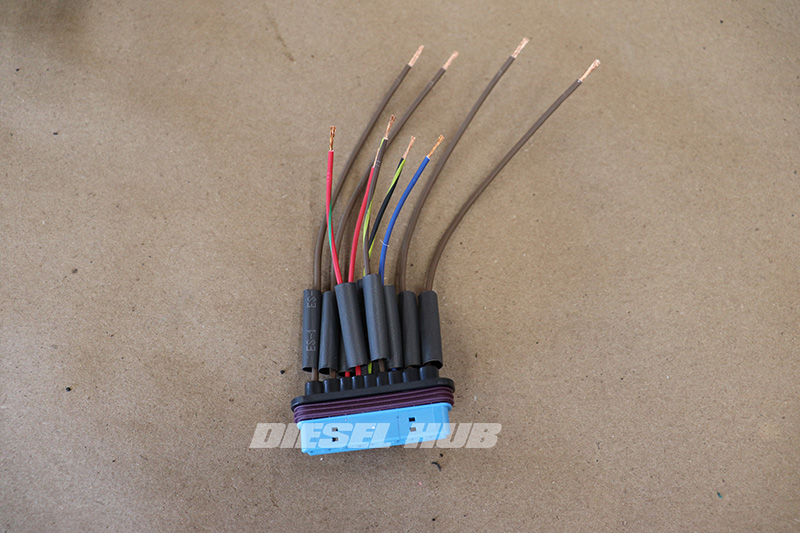
- Transfer the cut lengths from the old connector to the new one, but add 1/2 an inch to compensate for the stripped region overlap (cut replacement connector wires 1/2 inch longer than the length of the wires on the old connector).
- Install heat shrink tubing over each wire. Heat shrink tubing cannot be installed once the splice is complete.
- Use the old connector as a guide to identify which wire on the new connector corresponds with each wire on the harness. Not all pigtails have multi-colored wires, so use the connector terminal location as a reference point. Draw a quick diagram as necessary.
- I prefer to solder the wires in this repair because its the more resilient method, it preserves continuity in sensitive circuits, and the end result is significant less bulky than using butt splices.
- A third hand is an excellent tool that can keep the wires paired while soldering.
- If you have little experience soldering, practice on some spare wire to get a feel for the heat and solder inputs; grossly over-soldering wires together can result in a brittle splice and damage to the wire insulation.
- Solder or splice each wire together, going slow and repeatedly verifying that the wires are being matched correctly. Remember to use the old connector as a guide.
- During the process, always verify that the heat shrink tubing is installed before splicing. It is not uncommon to knock a piece off of a wire while maneuvering the connector. Once the splice is made, the heat shrink cannot be installed.

- Activate and secure each section of heat shrink tubing with a heat gun. Position the wires as necessary to ensure that heat does not damage the wire insulation or wiring harness coverings.
- Reinstall the shielding around the fuel injector wires.
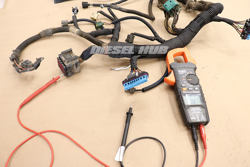
- Verify continuity and low resistance between the valve cover connector and main engine wiring harness connector (reference pinout diagrams in section above).
- This is the last line of defense in verifying that the splices are good and that the wires were correctly paired.
- Repeat for each connector that is replaced.

- Reassemble the harness with wire loom and tape things up as necessary.
- If removed, reinstall the engine harness in reverse order. The most critical aspect of installing the wiring harness is making sure that nothing will catch in the accessory drive belt.
- Recommend verifying the valve cover gasket/UVCH condition at this time. Breakout tool 190101 can be used without having to pull the valve covers.

