Applicable Models:
1994.5 - 1997 Ford F-250, F-350, F-Super Duty
1999 - 2003 Ford F-250, F-350, F-450, F-550 Super Duty
2000 - 2003 Ford Excursion
1995 - 1999 Ford Econoline E-350
2000 - 2003 Ford F-650, F-750
2000 - 2003 Econoline E-350, E-450, E-550
Applicable Engine(s):
7.3 liter Power Stroke V-8 (7.3 DIT)
The 7.3 liter Power Stroke uses hydraulically actuated, electronically controlled unit injectors (HEUI). Although somewhat defunct by modern standards, the HEUI injection system was once a state-of-the-art technology with many advantages, including very high operating pressure. The HEUI system relies on pressurized engine oil delivered through galleries in the cylinder head to each fuel injector to produce relatively high fuel injection pressures without a high pressure fuel pump; only low pressure fuel is supplied to the injectors.
A plunger inside the fuel injector body intensifies the force created by high pressure oil at one end to pressurize fuel on the opposite side. This form of mechanical advantage produces peak injection pressures (pressure prior to exiting the injector nozzle) up to 21,000 psi with only 3,000 psi of oil pressure. A high pressure oil pump, not fundamentally different than a small hydraulic pump, is responsible for producing and maintaining oil pressure for the injection system.
Oil pressure in the high pressure circuit is monitored by the ICP sensor and controlled by the IPR valve, a solenoid type actuator that exhausts excess pressure to the crankcase. The PCM is responsible for monitoring the performance of the system and controlling oil pressure based on various engine and vehicle inputs. The injectors themselves are mounted into brass sleeves secured in the cylinder heads. Engine coolant flows around these sleeves to provide cooling.
Since these injectors have independent working chambers for fuel and oil, the quality of these fluids can weigh heavily on the lifespan of these injectors. In my experience this type of injector, on average, has a service life of 150,000 miles. Some injectors will require replacement closer to 100,000 miles, others will make it 200,000 miles or more. Injectors can wear internally and begin to provide subpar performance (i.e. bleeding off pressure, poor spray pattern), one or more seals can fail (fuel mixing in the coolant and/or engine oil), or the electronic component of the injector can fail first. Prolonging fuel injector life requires being attentive to fuel and motor oil quality.
Diagnostics
Fuel injectors can be removed from the engine and tested at a specialized facility - local fuel injection shops typically offer this service or serve as an intermediary to the process. In lieu of leaving a vehicle disabled while the injectors are sent out, tested, and returned, there are other ways to determine the health of the fuel injectors.
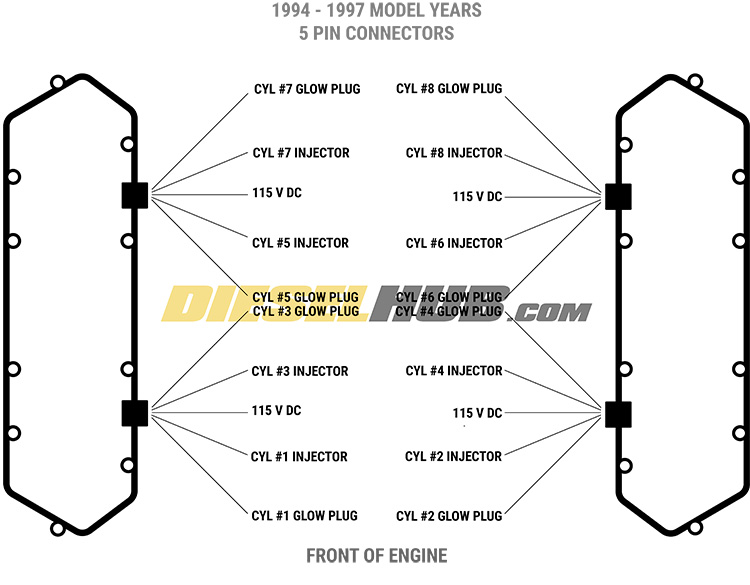
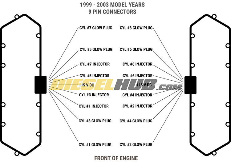
A bad solenoid can be determined by removing measuring the resistance across the solenoid. This can be done by removing the valve cover and testing directly at the injector, or by unplugging the UVCH pass-thru connector and probing the appropriate pins. A breakout tool can be used to aid in this process, as probing the valve cover gasket male pins can be tricky. If the latter test is performed, further diagnostics are necessary to ensure that it is not the UVCH or valve cover gasket that is causing the high resistance condition. Resistance should not exceed 3.6 Ohms for any injector solenoid. Figures 1 and 2 (below) provides pinouts for both early and late style valve cover gaskets/harnesses.
Note that the injector "buzz test" can save you time by identifying a weak injector solenoid without removing or disconnecting any component from the engine; it is a beneficial starting point, but requires a compatible scantool to run such special tests.
Buzz Test
Diagnostic tools can perform many special tests programmed into the PCM of the vehicle. The first step in evaluating injector health is to perform a buzz test. The injector buzz test is performed KOEO. Once initiated, it will briefly activate the injector solenoids in unison (all 8), and then actuate each solenoid individually in sequence, beginning with cylinder 1 and ending with cylinder 8. The objective is to listen for a weak "buzzing" noise and associate it with the appropriate cylinder. A healthy solenoid produces a strong, sharp buzz when it is actuated and a weak solenoid produces a low, dull buzz. The buzz test is an extremely quick and easy way to identify a weak injector solenoid.
Cylinder Contribution Test
The cylinder contribution test, also referred to as a power balance, percent delta, or PERDEL test, measures the contribution of each cylinder to the rotational speed of the crankshaft. This test is performed KOER. Once initiated, the PCM will monitor engine rpm and the injector firing sequence. It will record the change in engine speed relative to each combustion event from each cylinder. On the 7.3 liter Power Stroke engine specifically, the results are given as a percent of change in rotational speed for each cylinder. Ideally, there should be no changes greater than 5%. If the readings for one cylinder are high, there's a good chance that that fuel injector may be failing.
Injector Codes
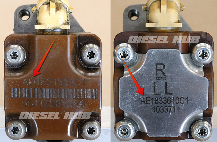
The injector code is the two letter prefix to the International-Navistar part number found at the top of the injector solenoid - "AD1831551C1" for example. It is used to distinguish between single and split shot fuel injectors and also identifies the original applications; different applications had different performance specs.
- AA - "AA" fuel injectors are found in all 1994 to 1995 model engines and all 1996 to 1997 engines equipped with the Federal emissions package (no California emissions package). This is a single shot injector.
- AB - "AB" fuel injectors are found in 1996 to 1997 engines with a California (CARB) emissions package and all early 1999 engines. This is a split shot injector.
- AC - "AC" fuel injectors are found in International T444E engines. While the 7.3 liter Power Stroke is a version of the T444E, this injector was not used in Ford vehicle applications. This is a single shot injector.
- AD - "AD" fuel injectors are found in all late 1999 to 2003 engines, but only in cylinders 1 through 7 (see AE/AF below for cylinder 8 injector). This is a split shot injector.
- AE/AF - "AE" and "AF" fuel injectors are found in all late 1999 through 2003 engines, but only in cylinder 8. This is known as a "long lead" injector. It was introduced to cure an abnormal "cackle" noise produced when the cylinder 8 injector fired. This is a split shot injector.
Single vs Split Shot
The injection event of a single shot fuel injector is incredibly simple - a single burst of fuel injects into the combustion chamber from the nozzle of the injector. Split shot injectors were first introduced for the 1996 model year specifically for engines that were required to meet CARB emissions regulations. The 49 State version of the engine continued to utilize single shot injectors until the late 1999 update.
A split shot injector provides two bursts of fuel for each combustion event. The first burst is of lower pressure and volume than the second burst. It forces a flame to begin propagating so that the second burst, which is of high pressure and greater volume, combusts more efficiently and reduces particulate emissions. As a byproduct, split shot fuel injectors tend to produce less engine noise at idle.
Long Lead Injector
The cylinder 8 "long lead" fuel injector is found in all late 1999 and newer 7.3 Power Stroke engines. It addresses cylinder 8 injector "cackle", a performance issue that produces an abnormal sound when the number 8 injector fires under certain conditions. The cause of this phenomenon is actually quite simple.
The 7.3 Power Stroke's firing order is 1-2-7-3-4-5-6-8. Odd numbered cylinders (1, 3, 5, and 7) are located on the passenger side while even numbered cylinders (2, 4, 6, and 8) are located on the driver side. Note that as the injectors fire, they alternate between the passenger and driver side banks, except when cylinder 8 fires. The cylinder 8 injector fires immediately after cylinder 6 in the firing order. Since cylinder 6 and 8 are located on the same bank, they share an oil rail and fuel gallery. Thus, the cylinder 6 injection event can cause a momentary drop in oil and fuel pressure for the cylinder 8 injector.
The long lead injector is designed to perform normally under these conditions. For late 1999 and newer Power Strokes, AD code fuel injectors are installed in cylinders 1 through 7 while cylinder 8 receives an AE or AF code long lead injector. Note that AD, AE, and AF injectors are all rated at a maximum flowrate of 140 cc and all are split shot injectors.
Injector Parts
| Component | Part Number | Remarks | |
|---|---|---|---|
| AA fuel injector | Alliant Power AP63800AA | [1],[2] | |
| AB fuel injector | Alliant Power AP63801AB | ||
| AC fuel injector | Alliant Power AP63802AC | ||
| AD fuel injector | Alliant Power AP63803AD | ||
| AE/AF fuel injector | Alliant Power AP63804AE | ||
| Fuel injector seal kit | Alliant Power AP0001 | [2] | |
| Injector sleeve set | Ford F4TZ-9F538-A | [3] | |
| UVCH | 1994 - 1997 | Ford F4TZ-9D930-K | [4] |
| 1999 - 2003 | Ford F81Z-9D930-AB | ||
| Valve cover gasket | 1994 - 1997 | Ford F4TZ-6584-A | |
| 1999 - 2003 | Ford F81Z-6584-AA | ||
[1] - Refer to injector code section above for applications; Alliant Power is the OE supplier for remanufactured Ford fuel injectors
[2] - Remanufactured fuel injectors include seals, not required to purchase separately. If injectors are removed and to be reused, seals must be replaced.
[3] - Injector sleeves are a press-fit but are required to be sealed to the cylinder head with Loctite 620 retaining compound
[4] - Valve cover gasket pass-thru connectors and injector wiring harness should be tested to verify good continuity; replace as necessary. For valve covers with two 5 pin pass-thru connectors, choose parts specified 1994 to 1997 model year. For valve covers with a single 9 pin pass-thru connector, choose parts specified 1999 to 2003 model year.
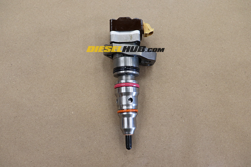
O-rings & Seals
Early Power Stroke fuel injectors required seven o-rings/seals to seal and isolate the oil and fuel passages. However, this was reduced to six seals sometime around the 1999 model year. The middle seal is now larger instead of using two and all injectors, regardless of model year, require only six seals. Figure 3 (below) identifies the various sealing components and where they belong on the injector.
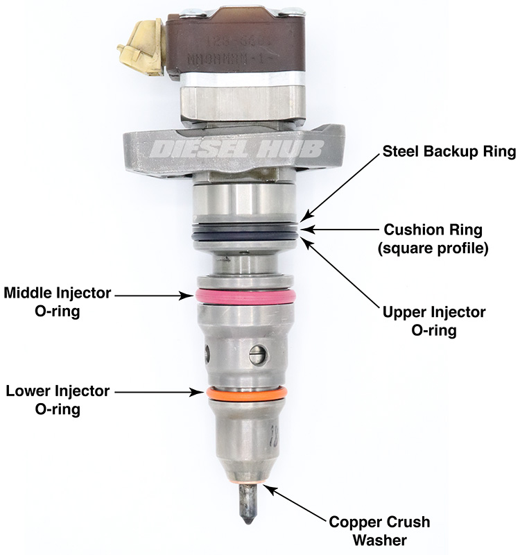
- Upper groove (farthest from nozzle, closest to solenoid) - One steel backup ring, followed by one rectangular backup o-ring, followed by one standard o-ring seal
- Middle groove - One o-ring seal
- Lower groove (closest to nozzle, farthest from solenoid) - One o-ring seal
- Lower sealing surface (just above nozzle) - One copper crusher washer
Each seal, including the copper crush washer, should be replaced anytime an injector is removed and to be reinstalled.
Required Tools
In addition to basic hand tools, a bore brush set is required if the injector sleeves are not to be replaced. Removal of the injectors will leave residual seal deposits inside the sleeves, and there is a chance for carbon deposits left by fuel and oil. The sleeves should be good and clean with a smooth finish before an injector is installed.
An extraction tool will also be necessary in order to evacuate fuel and oil from the cylinders before installing fuel injectors. When an injector is removed, fuel and oil will drain from their respective galleries and into the cylinder through the hole in the injector sleeve. Draining the fuel and oil galleries before removing the injector can reduce this effect, but the cylinders will still need to be evacuated or the engine could hydro-lock when it is cranked. Fluid extraction tools come in manual, pneumatic, and electric variations.
Injector Removal
Click any thumbnail to view fullsize, detailed image
- Disconnect both negative battery cables.
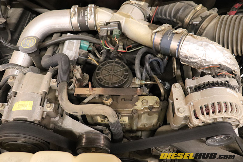
- If applicable, remove the plastic "Power Stroke" engine cover.
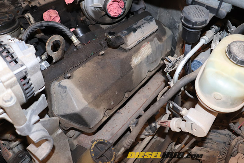
- Remove the valve covers; refer to valve cover removal instructions for additional guidance.

- Disconnect the electrical connectors from the fuel injectors and glow plugs, then remove the under valve cover harness/gasket assembly.

- Locate the (2) oil rail drain plugs in each cylinder head and remove them with an 1/8 inch hex (Allen) driver or key.
- The oil rail drain plugs are located between cylinders 1 and 3, 5 and 7 on the driver side. The passenger side plugs are positioned between cylinders 2 and 4, 6 and 8.

- Once both oil rail plugs have been removed, use a fluid extraction tool (recommend Mityvac pneumatic version) to extract engine oil as it drains from the rails and collects in the cylinder head. With a small enough hose, oil can also be extracted directly from the rail.
- Note that draining the oil rails as much as possible minimizes the amount of engine oil that will flood the combustion chambers when the fuel injectors are removed. Ideally, the fuel gallery would also be drained at this time for the same reason, but creating access to them is complicated and they are notorious for stripping so we'll deal with the fuel later in the procedures.

- Remove the oil spout from each injector with a 5 mm hex (Allen) driver or key.

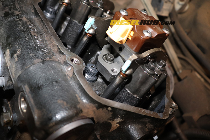
- Remove the lower fuel injector hold-down bracket (collar) retaining bolt with an 8 mm socket.
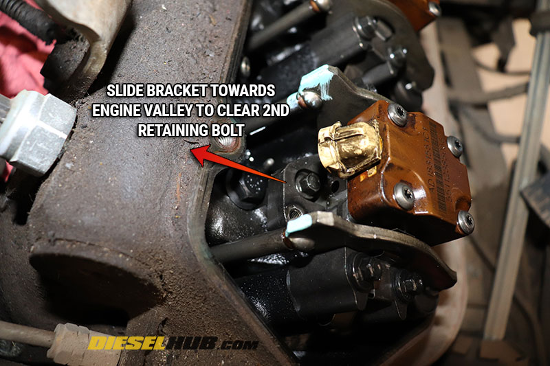
- Slide the fuel injector hold-down bracket towards the engine valley to clear the upper (shouldered) retaining bolt, then slide the bracket up and over the bolt so that it is clear.
- If necessary, loosen the upper fuel injector bracket retaining bolt with an 8 mm wrench. The bolt head is positioned beneath the fuel injector solenoid connector so a socket will not fit, but a thin profile 8 mm wrench will. This bolt only needs to be loosened if the bracket is being stubborn and will not maneuver over the shoulder of the retaining bolt.
- Pry the injector upwards out of the cylinder head by positioning a pry bar or large screwdriver beneath the hold-down bracket; do not pry on the injector itself.
- Don't be alarmed if a bit of leverage is needed during this step, as the o-rings have likely been seated for some time.
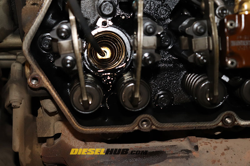
- Diesel from the fuel gallery and residual oil from the oil rail are going to rush into the combustion chamber once the injector seal is broken. After the injector is removed, immediately begin evacuating the combustion chamber with a fluid extraction tool.
- Verify that the copper crush washer came out with the injector. If it did not, fish it out of the sleeve.
- Repeat for the remaining cylinders.
- Remove each glow plug with a 10 mm deep socket.
Injector Installation

- If the fuel injectors are to be reused, remove the old o-rings without marring the surface of the injector, particularly the sealing areas.
- Remove the copper sealing washer at the injector nozzle. If it is missing, retrieve it from the injector sleeve.

- Keep the order of the o-rings as they are removed to make it easier to match the correct o-ring positions during installation of the new ones.
- Coat the replacement o-rings in clean motor oil, then install them onto the injector body.
- Lubricate the injector body and o-rings with clean motor oil, gently working around each o-ring to ensure there is no binding and the o-rings fit "comfortably" in their grooves.
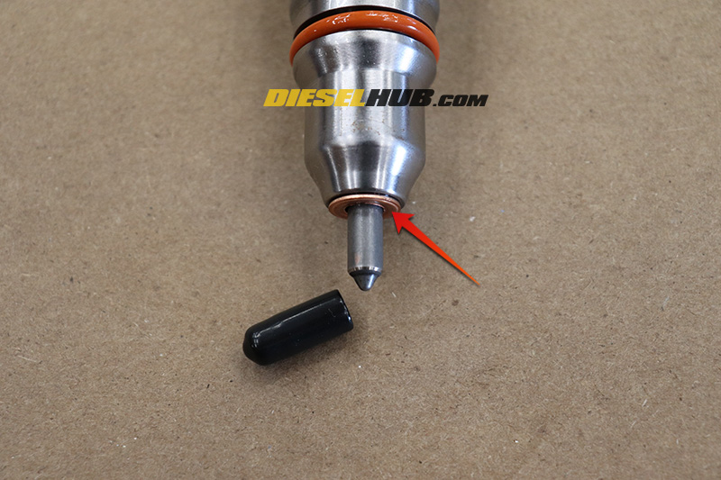
- If applicable, remove the protective cover from the injector nozzle and install the copper sealing washer (may be pre-installed on new or remanufactured injectors).

- If the injector sleeves are not to be replaced, an injector bore brush set is imperative.
- Thoroughly clean the interior of the injector sleeves with a bore brush.
- Evacuate or vacuum any debris that was dislodged from brushing. Obtaining a positive seal requires that the inside of the sleeves and clean and free of debris. Additionally, debris could infiltrate and disable the fuel injector.
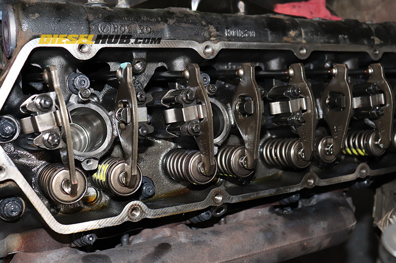
- It is advisable to torque the rocker arm pedestal bolts anytime the valve cover is removed because they have a tendency to loosen over time. The pedestal bolts require a 12 point, 8 mm socket and the torque spec is 20 ft-lbs.

- If removed, reinstall the upper injector retaining bracket bolt (nearest to engine valley) and torque to 120 in-lbs.
- Position the fuel injector into the sleeve and maneuver the slotted hold-down bracket over the upper retaining bolt.
- Slide the hold-down bracket towards the exhaust manifold to properly position the upper retaining bolt in the slot.
- The shoulder of the retaining bolt should be seated into the corresponding cup machined into the hold-down bracket.
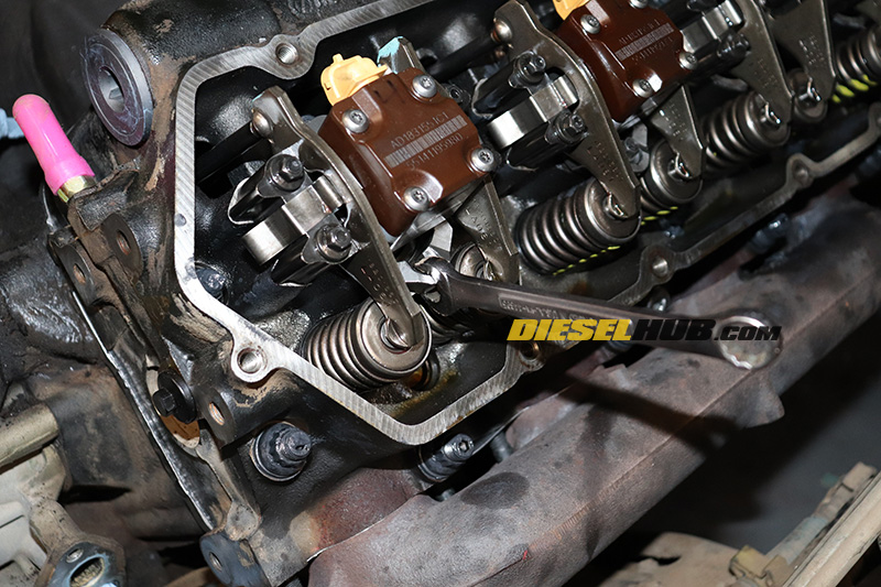
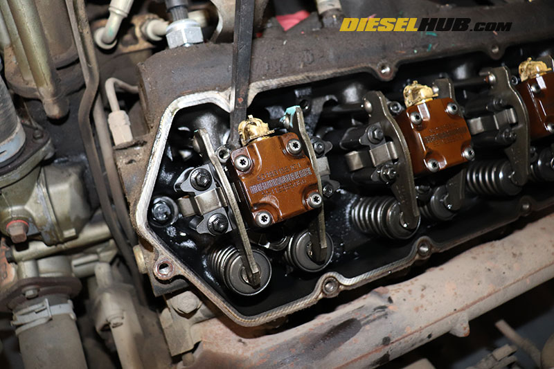
- Seat the fuel injector by using downwards force, leveraging a wrench on the hold-down bracket (pictured), or using Ford tool T94T-9000-AH2. This can be notably tricky for the rearmost cylinders.
- Install the lower retaining bolt; the fuel injector must be fully seated before torquing down the retaining bolt. Do not attempt to seat the injector using the retaining bolt. Do not hit or pry on the injector solenoid to seat the injector.
- Torque the retaining bolt to 120 in-lbs.
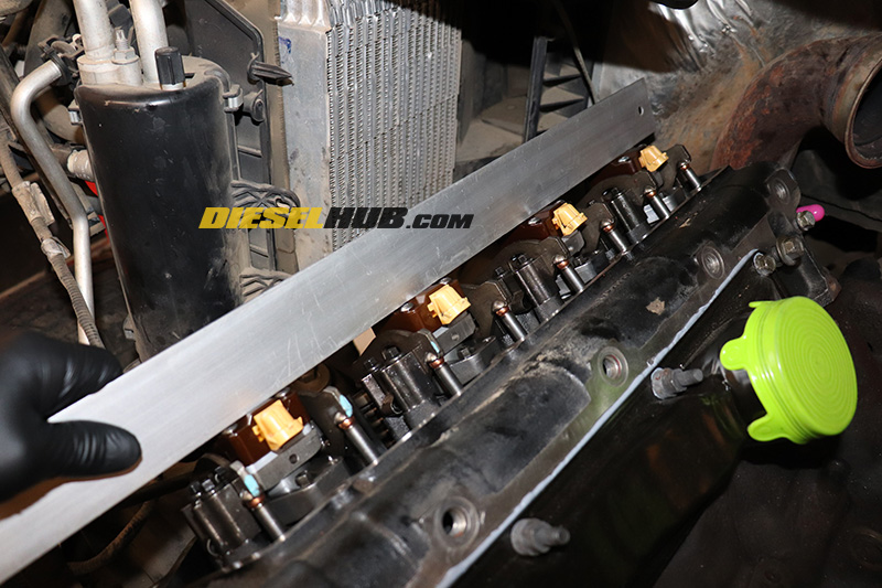
- Verify that the fuel injectors are properly seated using a straight edge laid across the solenoid covers. Some very small variance is acceptable, but this step will identify any injectors that are obviously not seated correctly.
- When the injectors seat properly, it is usually quite obvious.

- Reinstall the injector oil spout and torque the retaining bolt to 106 in-lbs.
- Repeat for all cylinders.
It is imperative that the combustion chambers are properly evacuated after the fuel injectors are replaced. Because of the angle at which the engine rests, oil and fuel will have a propensity to flow and collect in the rear (#7 and #8) cylinders. Severe engine damage will occur if excessive oil/fuel is left in the combustion chamber of any cylinder after the fuel injectors are installed. Complete evacuation is accomplished in the steps below by blowing any residual fluids out of the combustion chamber through the glow plug holes. All glow plugs must be removed for this step.
- NOTE - GLOW PLUGS MUST BE REMOVED
- Ensure that the accessory drive is clear and that there are no obstructions (i.e. rags, tools, etc) in the intake air pathway.
- Loosely install both valve covers - only a few fasteners are needed on each.
- Reconnect the batteries and crank the engine over for several seconds to finish evacuating the combustion chambers.

- Reassembly the remaining engine components in reverse order. Torque glow plugs to 124 in-lbs.
- Prime the engine oil and fuel systems before attempting to start the engine; operating the injectors dry may cause significant wear or damage.
- Changing the engine oil/lube oil filter is recommended since there is highly likely to be fuel contamination.
Applicable Torque Specs
| Component | Torque, ft-lbs | Torque, in-lbs |
|---|---|---|
| Injector hold down bolts | --- | 120 |
| Injector oil deflector spout | --- | 106 |
| Glow plug | --- | 124 |
| Rocker arm pedestal bolts | 20 | 240 |
| Valve cover bolts | --- | 97 |

