Applicable Models:
1999 - 2003 Ford F-250, F-350, F-450, F-550 Super Duty
2000 - 2003 Ford Excursion
1998 - 1999 Ford Econoline E-350
2000 - 2003 Ford F-650, F-750
2000 - 2003 Econoline E-350, E-450, E-550
Applicable Engine(s):
7.3 liter Power Stroke V-8 (7.3 DIT)
The 7.3 Power Stroke fuel filter housing is commonly referred to as the fuel bowl. On 1998 to 2003 model year engines it is mounted to the high pressure oil pump reservoir at the front of the engine. This later style housing is significantly more compact and less complex than that found on 1994 to 1997 model year engines. Fuel filtration, water separation, distribution, and pressure regulation are all handled at the fuel bowl.
Removal of the fuel bowl is necessary for many repairs, including gaining access to the high pressure oil pump and and the HPOP reservoir. A small fuel leak at the filter housing results in fuel collecting in the engine valley and, if severe enough, dripping off the rear, passenger side corner of the engine block.
Fuel System Flow & Operation
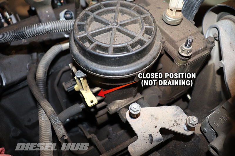
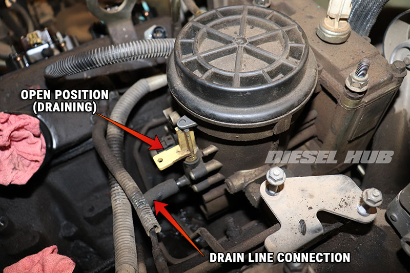
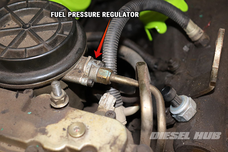
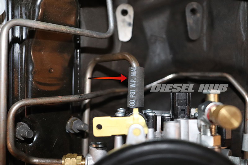
Referencing figure 1 below, the frame mounted electric fuel pump draws fuel from the tank and it enters the filter housing (1) at approximately 55 psi. Once the pressure in the housing has stabilized, excess fuel is returned to the tank at the fuel pressure regulator (2). The fuel pressure regulator is a simple spring-and-piston system that is forced off its seat at approximately 55 psi (assuming OEM spring in new condition). Item (3) represents the drain valve, which uses a flexible hose to connect to a hard-line that terminates at a location at the front, passenger side of the engine block (figure 3).
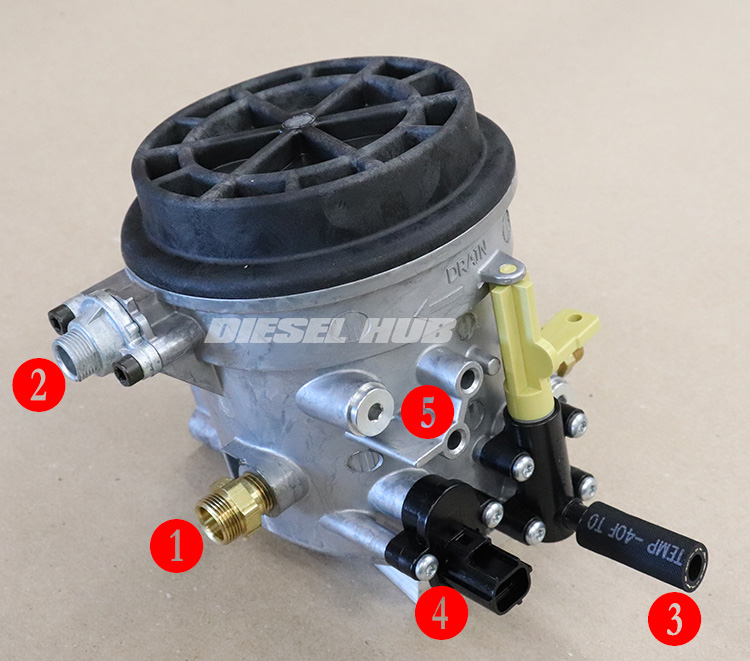
Water sinks and collects at the bottom of the fuel bowl because it is denser than diesel fuel. Fuel is drawn through the filter from the upper portion of the housing, thus the water settles at the bottom and remains there undisturbed until the bowl is drained. The water-in-fuel sensor (4) will make continuity across its terminals and trigger an alert if the water level in the bowl reaches its position. An access port (5) is incorporated into the rear of the housing so that a fuel pressure test adapter can be installed.
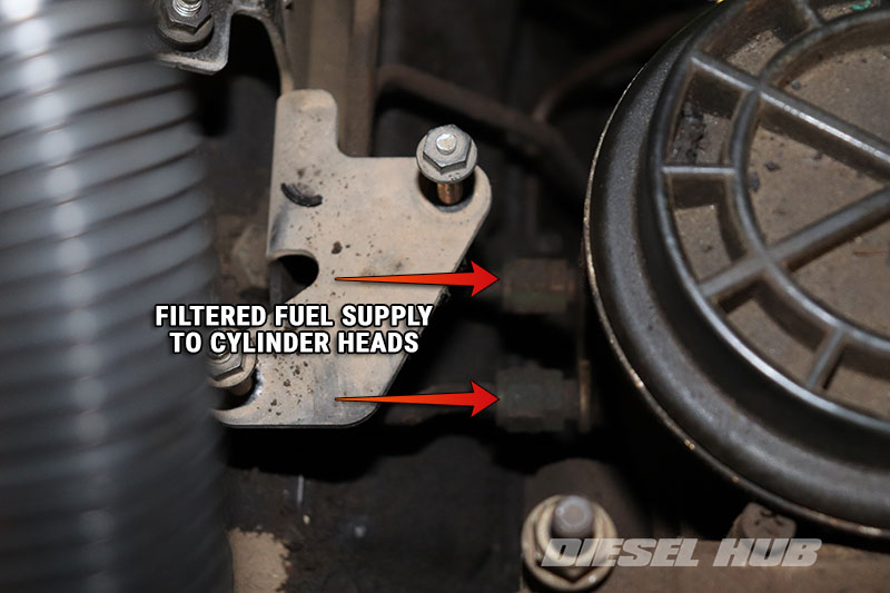
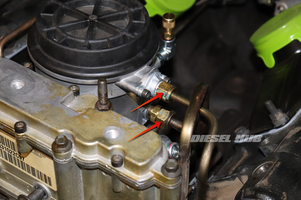
Referencing figure 2 below, fuel is forced through the filter element and exits through a pair of outlet fittings (6) on the lower, passenger side portion of the housing. Hard-lines connect to these fittings (6) and supply fuel to the left and right cylinder head fuel galleries. There is a second access port (7) incorporated into the outlet channel that a fuel pressure test adapter can be installed. There is an important distinction between the two access ports - (5) reads as-delivered pressure to the fuel bowl by the fuel pump and (7) reads pressure after the fuel has passed through the filter element.
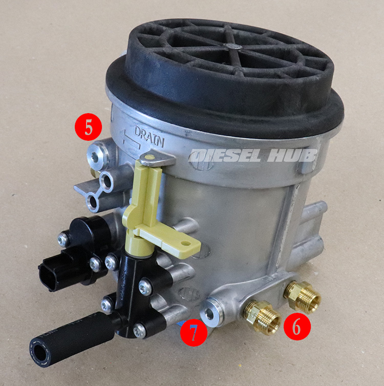
Under ideal conditions, the pressure differential between (5) and (7) is minimal. A large difference in pressure would suggest that the fuel filter was clogged, restricting the outlet flow and pressure. Turning the yellow handle on the drain valve drains the fuel bowl for the purpose of removing water from the housing, relieving residual pressure before removing the cap, and to reduce spillage during service. Figure 3 below identifies the location in which the metal drain line terminates.
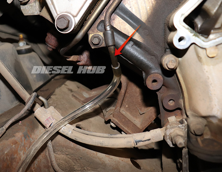
Note that a 5/16 inch ID hose can be attached to the metal hard-line permanently. When not in use, tuck the hose into the frame rail for safe keeping. If a container is not in place and the drain valve is opened, fuel will drain on the engine, ground wire, steering components, frame, etc. Attaching a hose such that a container can be placed on the ground is both practical and convenient.
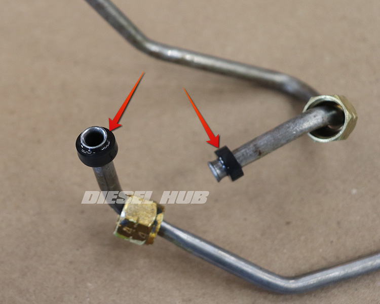
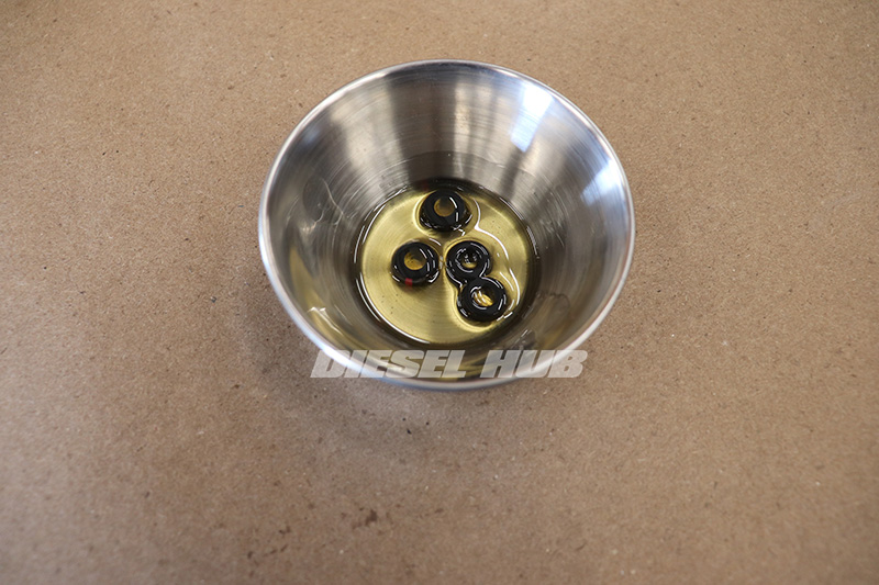
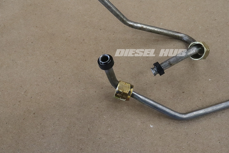
Compression Sleeves
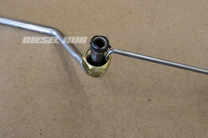
The 1999 to 2003 fuel filter housings use Parker Vibra-Lok fittings. This is a threaded type connection in which a rubber sleeve is compressed between the threaded nut and the flare on the fuel line. The compression sleeve is responsible for final sealing - the threads are not designed to be the primary sealing mechanism. These sleeves become hard, brittle, and deteriorate over time. Fuel leaks at the hardline-to-filter housing connections are most commonly the result of a compromised compression sleeve. The most economical way to acquire these is as a set (see fuel bowl compression sleeve kit).
Fuel Filter Housing Parts
| Description | Part Number(s) | Remarks |
|---|---|---|
| Fuel bowl assembly | Motorcraft FG-1057 | --- |
| Fuel filter cap | Ford F81Z-9G270-BA | --- |
| Fuel filter element | Motorcraft FD-4596 | --- |
| Drain valve | Ford F81Z-9A153-AA | [1] |
| Compression sleeves | Dieselply DP-1610K | [2] |
| Drain valve to hard-line hose | Dieselply DP-163101 | [3] |
| Fuel pressure test adapter | Dieselply DP-160501 | [4] |
[1] - Assembly, replace if old drain valve is damaged
[2] - Complete kit, services each connection at the filter housing and at each cylinder head
[3] - Hose can become hard and brittle with age; replace as necessary to prevent leaks while draining the fuel bowl
[4] - Includes adapters for temporary and permanent installation, fits standard 1/4 inch flare test equipment
How to Remove the Fuel Filter Housing
Click any thumbnail to view fullsize, detailed image
- Disconnect both negative battery cables.
- Drain the fuel bowl into a suitable container.
- Loosen the fuel bowl cap with an appropriate tool (recommend OTC 6760).
- Disconnect and remove the exhaust backpressure sensor to create access to the filter housing mounting bolts that pass through the high pressure oil pump reservoir.
- Once the housing has drained completely, close the drain valve.
- Locate the drain valve to hard-line connection at the lower rear portion of the filter housing.
- Place some rags in the engine valley beneath the drain valve.
- Disconnect the small black hose from the drain valve fitting.
- Disconnect the water-in-fuel sensor located next to the drain valve outlet.
- Disconnect the engine oil temperature sensor and position the connector/wire away from the fuel pressure regulator.
- On the driver side of the housing, remove the fuel line from the fuel pressure regulator using a 5/8 flare nut wrench.
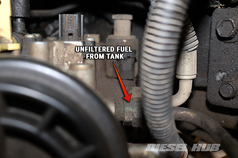
- Beneath the fuel pressure regulator, locate and disconnect the fuel supply line (inlet) using a 3/4 flare nut wrench.
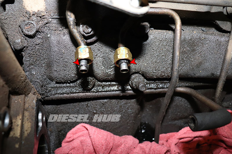
- On the passenger side lower portion of the housing, remove the (2) outlet fittings with a 9/16 flare nut wrench.
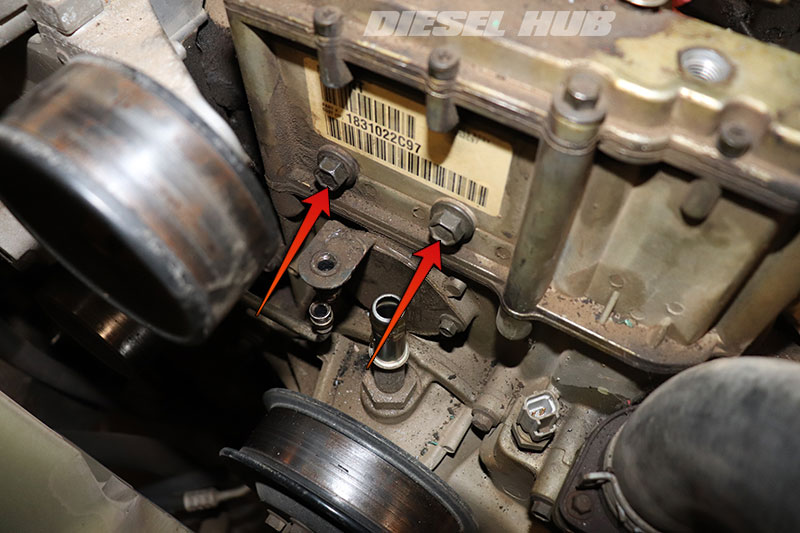
- Remove the (2) fuel bowl mounting bolts that pass through the HPOP oil reservoir with a 13 mm socket or wrench. Note that these bolts are isolated from oil in the reservoir, thus it does not have to be drained.
- Maneuver the fuel filter housing out of the engine compartment.
- Trace the (2) lines on the passenger side and disconnect them at each cylinder head.
- Plug the cylinder head fittings to prevent debris infiltration; these are downstream of the filter and any contaminants that enter these fittings will enter the fuel galleries in the cylinder heads.
How to Install the Fuel Filter Housing
- Carefully remove the old sealing sleeves from each of the hard-lines (from the hoses that were removed and those that are still mounted to the engine).
- Clean the fittings and threads with brake/carb cleaner.
- Do not allow remnants of the sealing sleeves to become lodged in the fuel lines.
- Thoroughly coat the replacement sleeves in clean motor oil, which will aid in installing them onto the fuel lines and help obtain a more positive seal when they are cinched down.
- Install the new sleeves onto each fuel line.
- The sleeve needs to be positioned over the flare portion of the line, but the threads will not catch the opposing fitting if the sleeve is pushed to far down the line.
- Reinstall the left and right bank fuel lines at the cylinder heads, but do not fully tighten the threads.
- Maneuver the fuel bowl into place and line up then install the drain line connection (small black hose).
- If this hose is hard, brittle, or fits loosely on the drain valve petcock, it should be replaced (see DP-163101).

- Position and start threading in the filter housing mounting bolts through the HPOP reservoir, but do not fully tighten.
- Leaving the fuel bowl loose will help start all the fuel line connections.
- Reattach all fuel lines (two on driver side, two on passenger side), starting the nut by hand to prevent cross-threading.
- Do not put final torque on the fuel line fittings until the fuel bowl mounting bolts have been cinched down.

- Snug down the fuel filter housing mounting bolts; do not overtighten.
- Snug down each of the (4) fuel line connections; do not overtighten the connections.
- Snug down the fuel line connections at each cylinder head.
- Reinstall the exhaust backpressure sensor.
- Reconnect the water-in-fuel and engine oil temperature sensors.
- Replace the fuel filter, then prime the fuel system and check for leaks.

