Applicable Models:
1994.5 - 1997 Ford F-250, F-350, F-Super Duty
1999 - 2003 Ford F-250, F-350, F-450, F-550 Super Duty
2000 - 2003 Ford Excursion
1995 - 1999 Ford Econoline E-350
2000 - 2003 Ford F-650, F-750
2000 - 2003 Econoline E-350, E-450, E-550
Applicable Engine(s):
7.3 liter Power Stroke V-8 (7.3 DIT)
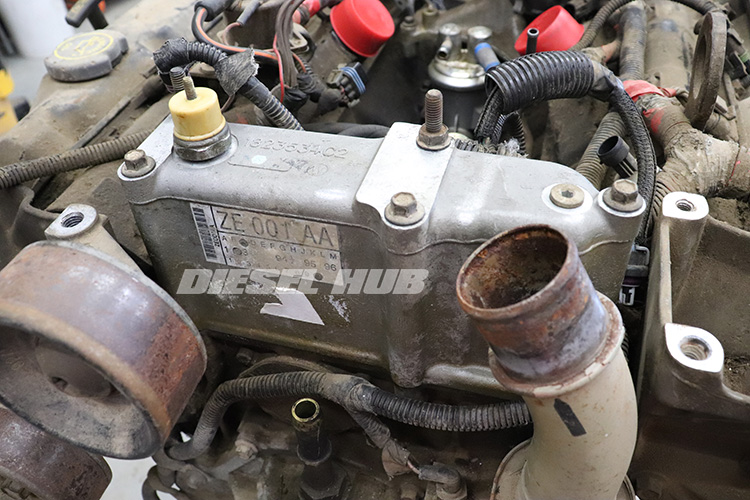
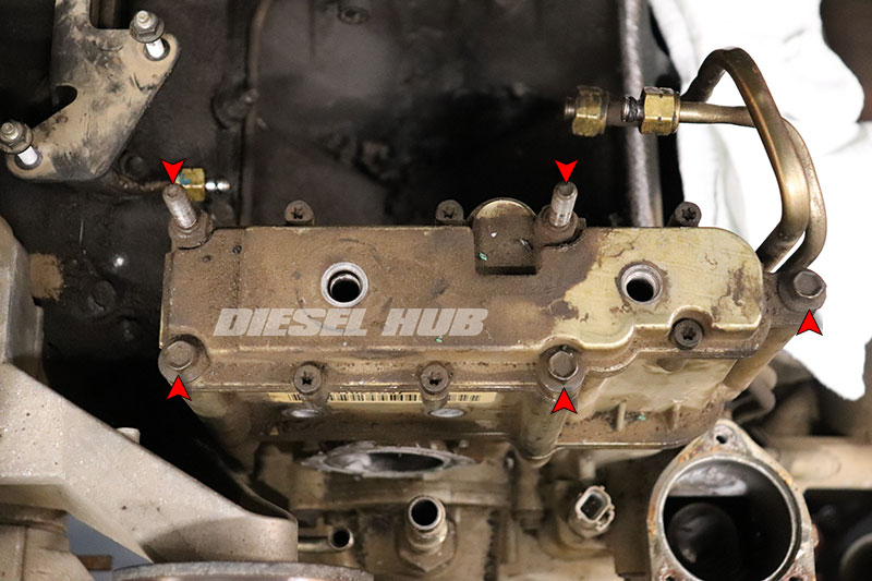
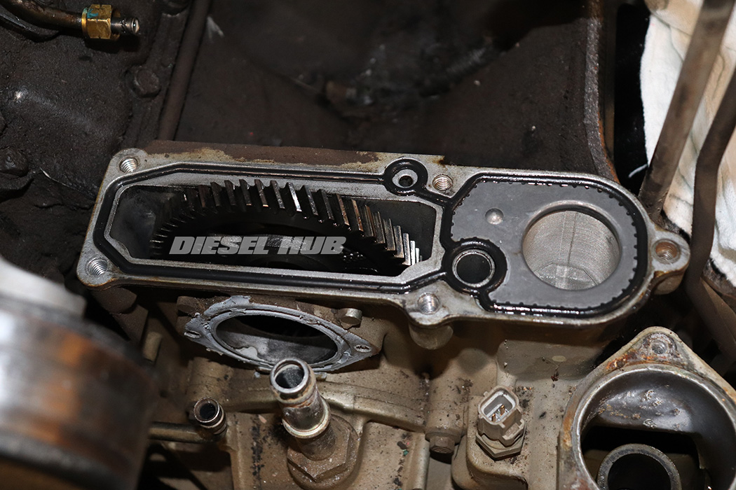
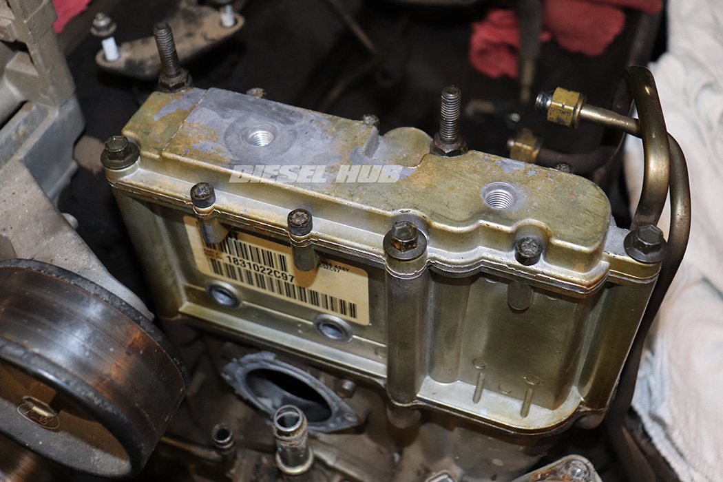
The high pressure oil pump reservoir is a cast aluminum repository that mounts above the HPOP gear system and in front of the HPOP. Its purpose is to maintain a continuous supply of oil to the pump for quick starting, to inhibit air intrusion of the high pressure oil circuit, and to prevent wear associated with oil starvation. The reservoir holds between 3/4 to 1 quart of engine oil at all time. This supply of oil is prevented from draining back into the crankcase by a check valve in the circuit and thus is not drained during oil changes.
Preventing air intrusion and avoiding oil starvation are critical to both the swash-plate type hydraulic pump as well as the internal components of the fuel injectors. During normal operation, the HPOP draws oil from the reservoir and the supply is perpetually replenished through the lube oil circuit. While the engine is cranking (being started), however, lube oil pressure and flow is both diminished and unstable.
As the engine is cranking oil flows through a dedicated and much shorter circuit, past the anti-drainback valve (spring loaded ball), and into the reservoir - this oil is unfiltered. As the engine continues to crank and oil pressure stabilizes, the anti-drainback valve returns to its original position, blocking off the unfiltered circuit. At this stage, the reservoir is being replenished with filtered engine oil from the main crankcase gallery. Once the engine is started, the HPOP oil supply continues to be replenished through the filtered circuit.
Model Year Differences
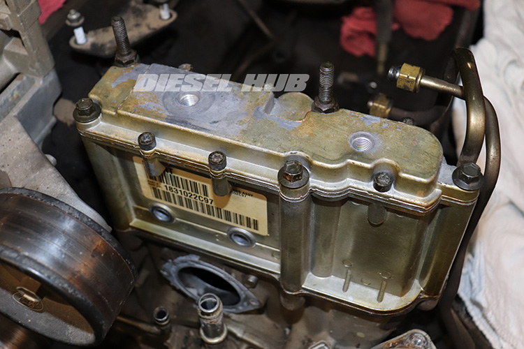
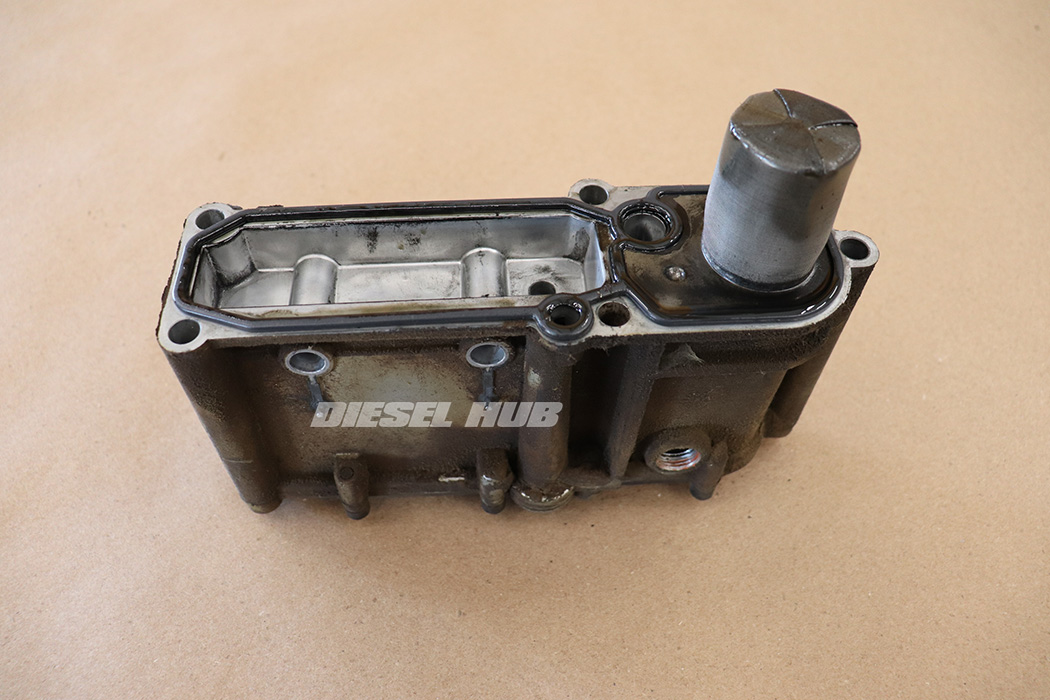
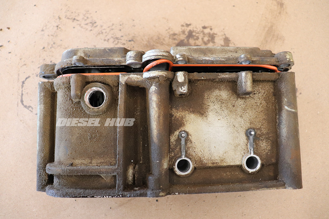
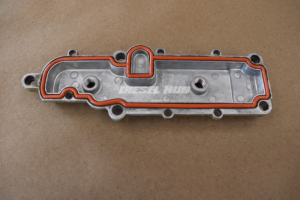
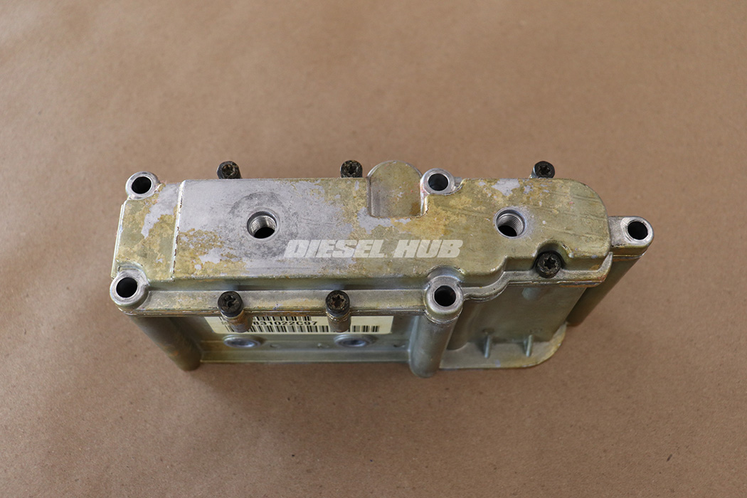
1994 to 1997 model year 7.3 Power Stroke engines utilized a one piece reservoir (figure 1 below) while a two piece reservoir (figure 2 below) was introduced for 1999. The two piece reservoir has a removable "lid" that allows the reservoir to be cleaned thoroughly (when it is removed to be resealed, for example). The internal structure of the one piece reservoir leaves blind areas that cannot be practically reached with cleaning brushes or rags.
There are two versions of the single piece reservoir. Early reservoirs used a tapered thread (NPT) oil pressure sensor and inspection port. These were also originally sealed on the "splash side" (above the pump drive gear) with RTV sealant and on the pressure side with a molded gasket. For the 1996 model year, International changed the casting to incorporate a standpipe and changed to a new oil pressure sensor and inspection plug that used straight threads and o-ring seals. Additionally, this newer version uses a one piece molded gasket to seal both chambers of the reservoir.
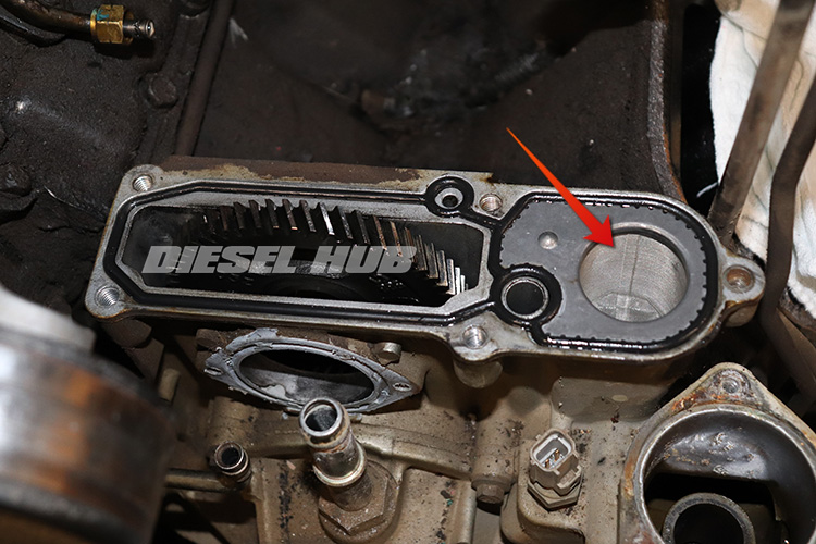
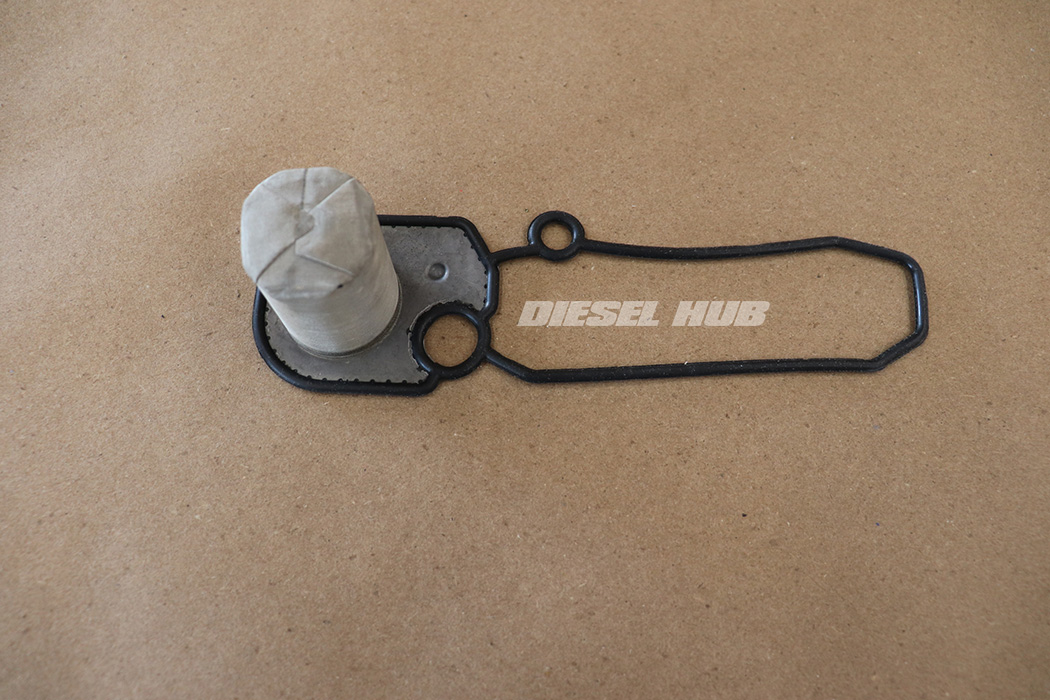
For the 1999 mid-model year upgrade (1999.5), International incorporated an integral filter screen (figure 3 below) into the lower sealing gasket of the reservoir. The screen exists to catch any large debris that could have made its way through the unfiltered oil circuit during initial startup. The gaskets are not interchangeable - a reservoir that originally came with the screen must be replaced like-for-like and reservoirs that did not feature this screen cannot be installed with one - there is no cross compatibility. Owners of 1999 model year vehicles must check to verify whether or not their unit requires the screen.
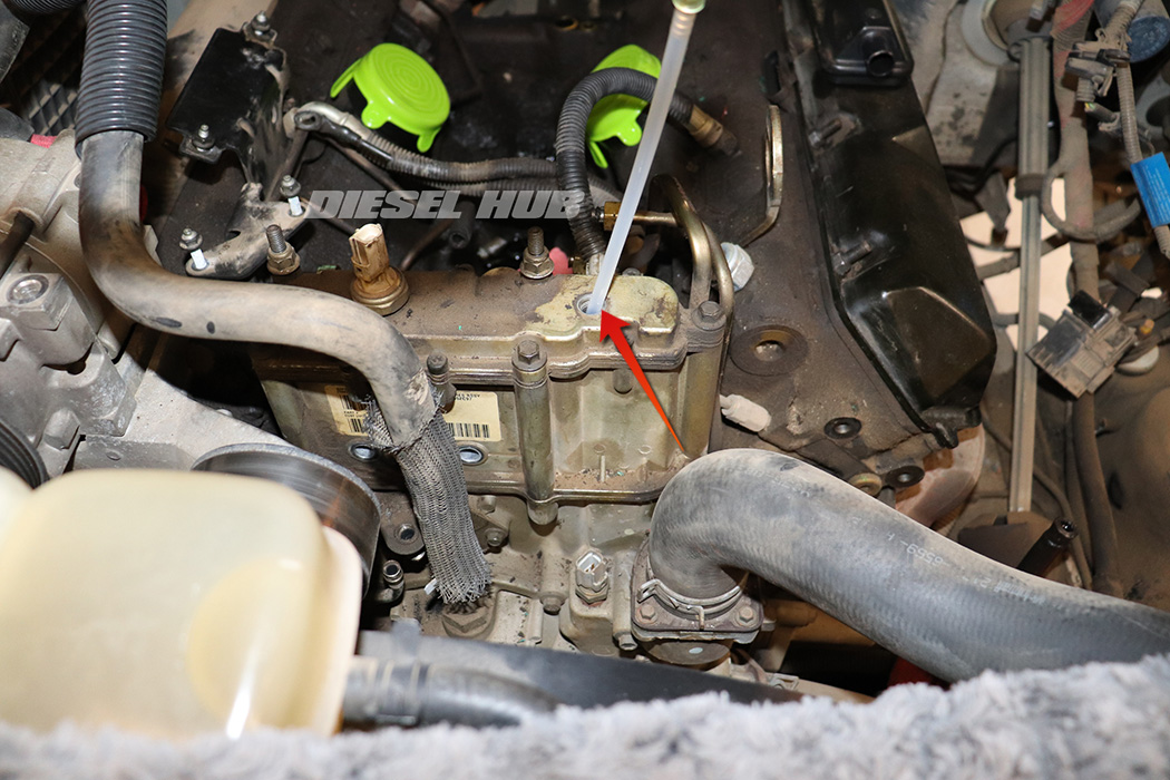
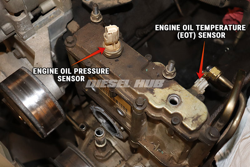
Regardless of model year and type, all reservoirs had an oil pressure sensor, oil temperature sensor, and inspection port integrated into the high pressure oil pump reservoir. The locations of these components are also the same - oil pressure sensors are mounted through the top of the reservoir towards the passenger side, oil temperature sensors are mounted through the rear of the reservoir on the driver side, and the inspection port is positioned through the top of the reservoir towards the driver side.
HPOP Reservoir Parts
| Component | Part Number(s) | Remarks |
|---|---|---|
| Lower gasket, 1994-1995 engines | Ford F4TZ-6619-A | [1] |
| Lower gasket, 1996-1999 engines | Ford F6TZ-6619-AA | [2] |
| Lower gasket, 1999.5-2003 engines | Ford YC3Z-6619-BA | [3] |
| Upper gasket, 1999-2003 engines | Ford F81Z-6619-AA | [4] |
| Fuel sleeve kit, 1999-2003 engines | Dieselply DP1610K | [5] |
[1] - Seal "splash side" of reservoir with Motorcraft TA-31
[2] - Molded gasket without screen; must replace like-for-like
[3] - Molded gasket with filter screen; must replace like-for-like
[4] - Two piece reservoirs only, 1999 to 2003 model year engines
[5] - Fuel filter housing is mounted to the reservoir on 1999 to 2003 engines; replace all sealing sleeves before reinstalling the filter housing
HPOP Removal, Disassembly, & Installation
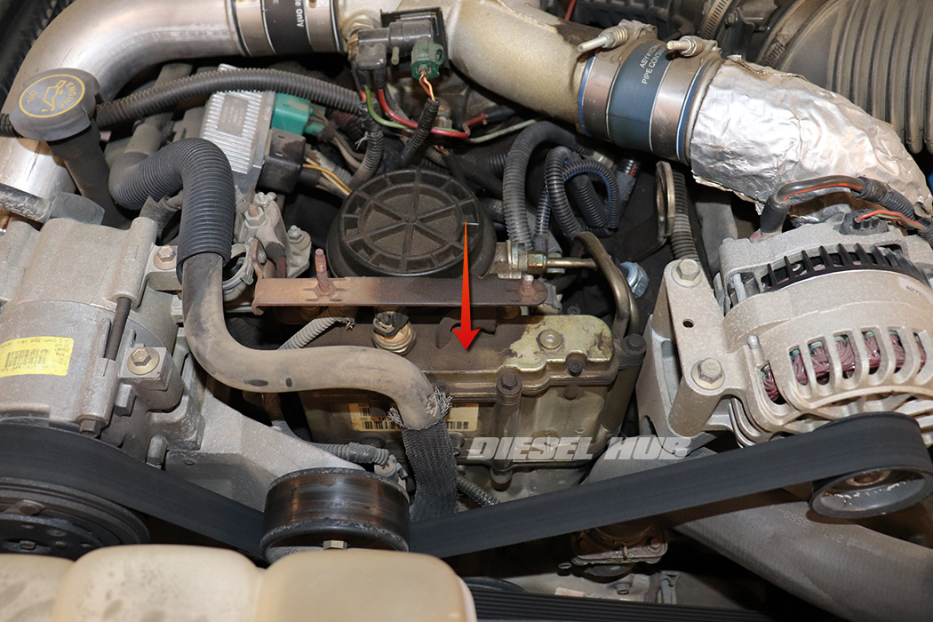
Unless otherwise noted, the following steps are applicable for all 7.3 Power Stroke engines. For these purposes, when a procedure is noted for early engines it refers to an engine where the EBP sensor is located at the rear of the reservoir towards the passenger side. Late engines will be a reference to an engine where the EBP sensor is located in front of the reservoir mounted to the HPOP drive gear access cover.
Click any thumbnail to view fullsize, detailed image
- Disconnect both negative battery cables.
- If applicable, remove the plastic engine cover and bracket.
- Remove the accessory drive belt (late engines only).
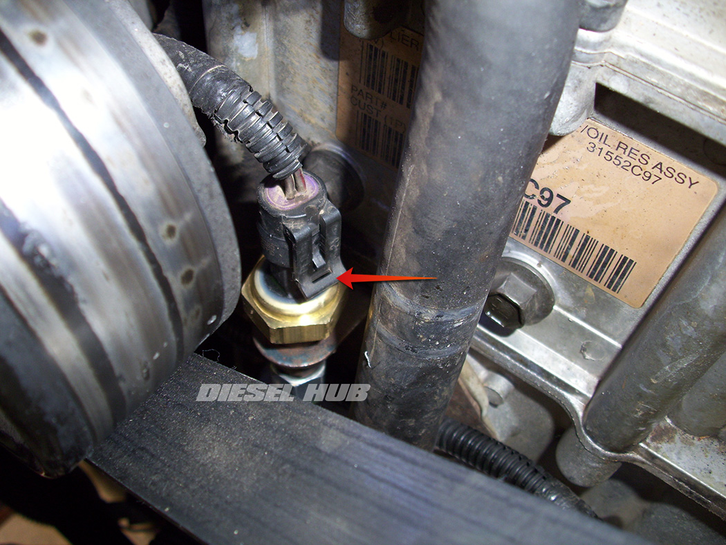
- Disconnect the oil pressure sensor (top of reservoir) and oil temperature sensor (rear, driver side of reservoir).
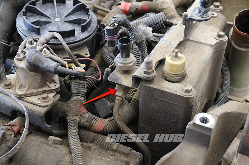
- Disconnect the exhaust backpressure (EBP) sensor connector and remove the EBP tube at the bracket fitting with a 5/8 inch flare-nut wrench.
- Remove the (2) nuts that secure the EBP sensor bracket to the HPOP reservoir with a 13 mm socket.
- Remove the EBP sensor bracket assembly from the reservoir and set aside.
- Disconnect the EBP sensor and position the connector away from the work area.
- Remove the EBP sensor; see 7.3 EBP sensor removal for detailed procedures.
- If desired, drain the radiator and remove the heater core supply hose from the water pump nipple on the top of the water pump. It is entirely possible to work around the hose but it does interfere to some degree.
- We've removed the hose to provide more detailed visuals in subsequent steps.
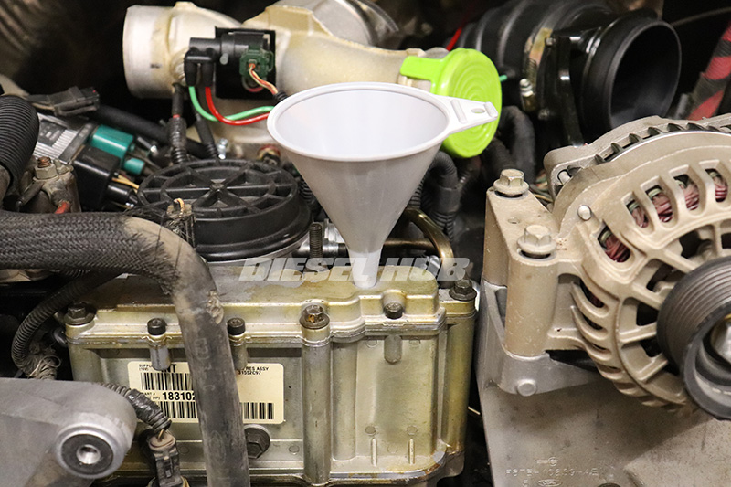
- Drain and then remove the fuel filter housing from the engine compartment; refer to 7.3 Power Stroke fuel bowl removal for detailed procedures.
- For 1999 to 2003 engines, the fuel filter housing mounts to the reservoir and thus must be removed.
- For 1994 to 1997 engines, the filter housing is mounted in the engine valley and does not need to be removed.
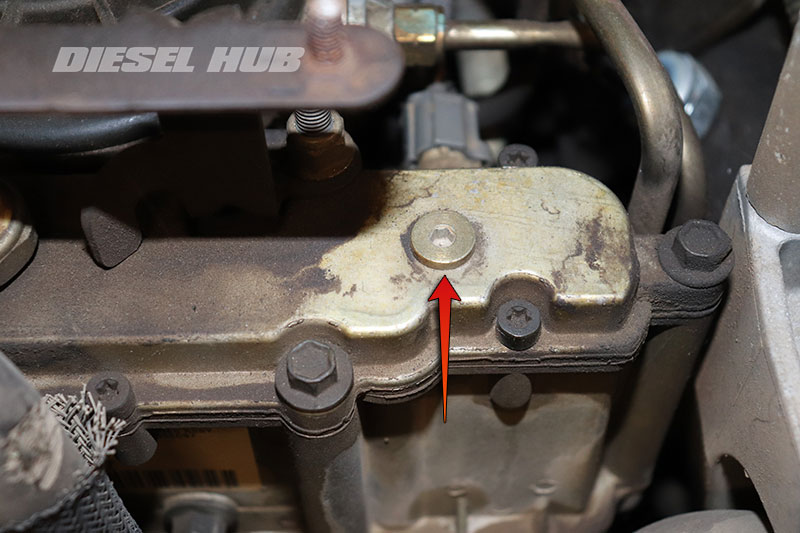
- Remove the HPOP reservoir inspection plug with a 3/16 inch hex (Allen) driver or key (top, driver side of HPOP reservoir).
- Use a fluid extraction tool (recommend Mityvac MV7102) to extract the engine oil in the HPOP reservoir through the inspection port.
- If the oil is not extracted from the reservoir, it will flood the engine valley and cover the front of the engine when the reservoir seal is broken.
- The reservoir holds approximately 3/4 to 1 quart of engine oil.
- Loosen the oil pressure and oil temperature sensors with a 1-1/16 inch deep socket, crowfoot wrench, or sensor socket.
- It can be difficult to break these sensors free when the reservoir is on a workbench.
- By loosening them while the reservoir is secured to the engine, they will be easy to remove later.
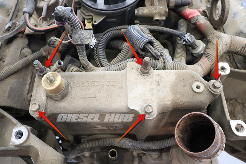
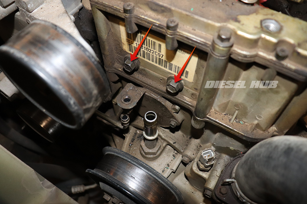
- Remove the (2) studded bolts with a 13 mm deep socket.
- Remove the (3) flange bolts with a 10 mm socket.
- Pull upwards and gently rock side-to-side to unseat the reservoir gasket and remove the reservoir from the engine.
- 1994 and 1995 model year engines will take significant more effort to break the silicon seal than later engines with a molded gasket.
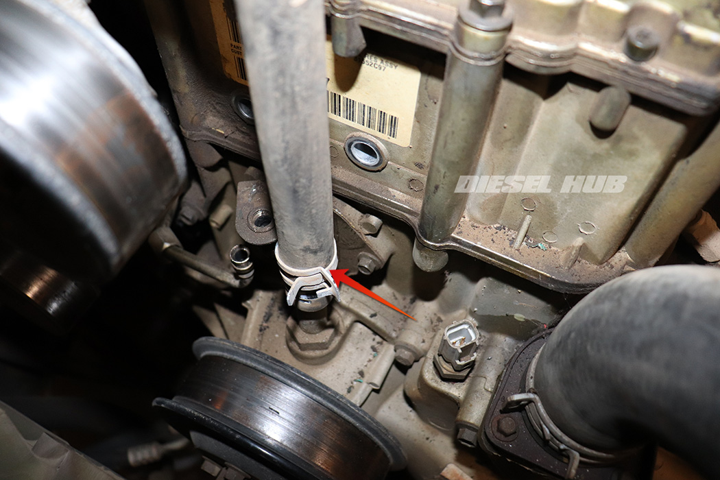
- Break loose, but do not remove the (6) Torx headed fasteners with a T-30 Torx driver/bit.
- Remove the (2) studded bolts with a 13 mm deep socket.
- Remove the (3) flange bolts with a 10 mm socket.
- Pull upwards and gently rock side-to-side to unseat the reservoir gasket and remove the reservoir from the engine.
- Place the HPOP reservoir on a work bench and remove the oil pressure and oil temperature sensors.
- Remove the molded gasket from the bottom of the reservoir (if applicable).
- For 1994 and 1995 model engines, remove all remnants of silicon sealant from the sealing surfaces.
- Remove the (6) Torx fasteners from the top of the reservoir with a T30 Torx driver/bit.
- Carefully separate the top cover from the lower portion of the reservoir.
- Do not mar the sealing surfaces. If prying is necessary, use a utility knife and work the blade around the reservoir.
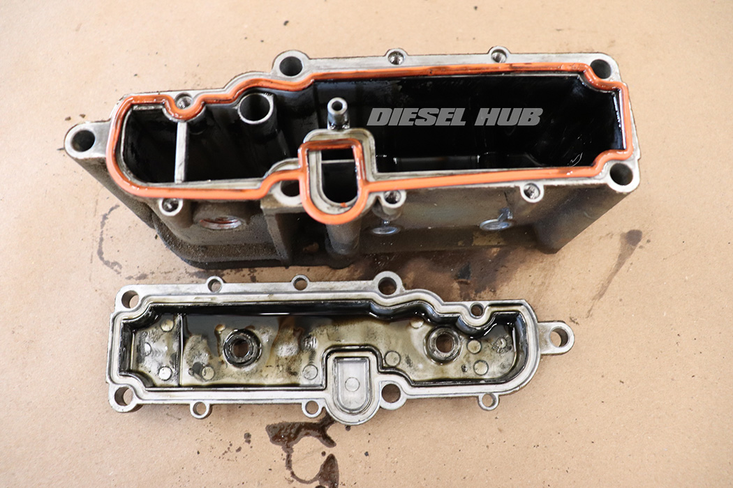
- Discard the reservoir cover gasket(s).
- Thoroughly clean all components, inside and out. A mild solvent or heavy degreaser is preferred.
- If a water based degreaser is used the parts must subsequently be cleaned with a solvent (such as brake cleaner) and dried thoroughly before reinstallation.
- All gasket mounting surfaces must be perfectly clean to ensure a robust seal.
- Thoroughly lubricate the reservoir top cover gasket with clean motor oil, then install it into the grooves on inside of the cover.
- Reinstall the top cover, ensuring that the gasket seats properly, evenly, and does not become pinched.
- Gently snug all bolts in an alternating fashion.
- Torque the fasteners between 75 and 95 in-lbs in an alternating fashion.
- Thoroughly lubricate the lower reservoir gasket with clean engine oil.
- Gaskets must be replaced like-for-like; do not attempt to put a screened gasket in a reservoir that did not originally include a screen.
- Position the reservoir gasket into place.
- These gaskets often hold some "memory" as a result of the method they are packaged, thus it may be necessary to work it flat.
- 1994 - 1995 engines, use Motorcraft TA-31 RTV sealant on the non-gasket side of the reservoir flange.
- For screened gaskets, the filter screen inserts downwards into the front cover, not upwards into the reservoir.
- Reinstall the high pressure oil pump reservoir, ensuring that the gasket is installed properly and was not pinched.
- Reinstall the reservoir mounting bolts and snug them in an alternating pattern.
- Torque all mounting bolts to 18 ft-lbs.
- Reinstall the oil pressure and oil temperature sensors.
- Reassemble the engine as applicable in reverse order.
- Refill the high pressure oil pump reservoir with new, clean motor oil.
- The oil level in the reservoir should be approximately 1 inch from the bottom of the inspection port.
- The reservoir will hold between 3/4 and 1 quart of oil.
- Recommend replacing the engine oil and oil filter after starting engine and checking for leaks.

