Applicable Models:
1994.5 - 1997 Ford F-250, F-350, F-Super Duty
1999 - 2003 Ford F-250, F-350, F-450, F-550 Super Duty
2000 - 2003 Ford Excursion
1995 - 1999 Ford Econoline E-350
2000 - 2003 Ford F-650, F-750
2000 - 2003 Econoline E-350, E-450, E-550
Applicable Engine(s):
7.3 liter Power Stroke V-8 (7.3 DIT)
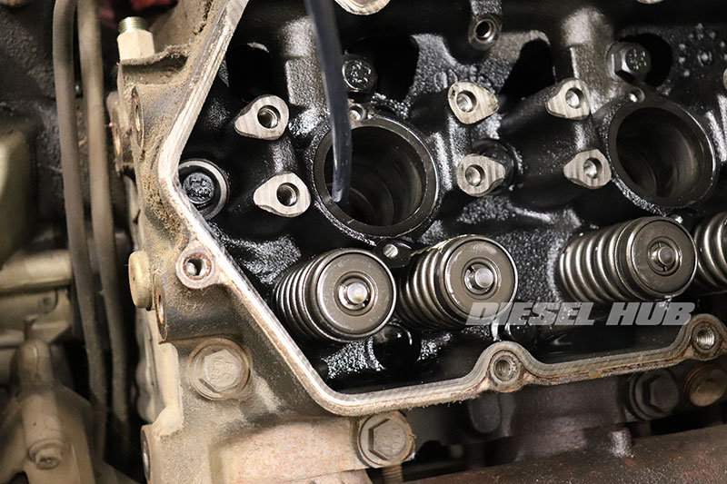
Each fuel injector on a 7.3 Power Stroke engine is installed into a brass sleeve (figure 1 below) that facilitates heat rejection around the nozzle assembly. Engine coolant flows around the outer circumference of each sleeve, also referred to as a cup, to help cool the injector. The sleeves are pressed into a bore machined into the cylinder head and a positive seal is ensured by applying retaining compound to the upper and lower contact surfaces.

The lower injector o-ring seals against the wall of the brass sleeve while the remaining o-rings seal against the walls of the cylinder head cavity. This series of o-rings is responsible for separating and containing the fuel and high pressure oil passages. The injector sleeves are prone to work hardening over time and it is not uncommon for a crack to develop due to vibration and heat exposure.
The most prominent symptom of a cracked (or leaking) injector sleeve is fuel present in the cooling system. This occurs because the fuel system operates at a nominal 55 psi and the cooling system operates at a much lower pressure (< 20 psi). Under these conditions fuel, at a higher pressure, will have the propensity to infiltrate the cooling system and not the other way around.
Replacing injector sleeves requires one of many available special tools that can securely hold the cup during removal and facilitate installation without deforming or damaging the part. Because this repair is relatively invasive, it is advisable to replace the sleeves in a complete set of (8). It is also quite likely that one failed sleeve is a precursor to future failures in the remaining (7). Furthermore, injector seals should not reused once an injector is pulled from the sleeve and each o-ring on each injector removed should be replaced.
Associated Parts
| Component | Part Number | Remarks |
|---|---|---|
| Injector sleeve set | Ford F4TZ-9F538-A | [1] |
| Injector o-ring set | Alliant Power AP0001 | [2] |
| Retaining compound | Loctite 620 | [3] |
| Economy sleeve puller/install tool | EVT444E CTA Tools 3875 |
[4] |
| Bore brush set | HG-3252 | [5] |
| Cooling system cleaner | Motorcraft VC-9 | [6] |
| Engine coolant | Motorcraft VC-5 | [7] |
[1] - Packaged as a complete set of (8) injector sleeves
[2] - Quantity (1) services a single injector; (8) sets needed to service all fuel injectors
[3] - Required, sleeves will not seal properly without retaining compound
[4] - More expensive options are most practical for career technicians, economical options work well enough
[5] - Required to properly clean the cylinder head sealing surfaces
[6] - Necessary if fuel or oil has contaminated the cooling system
[7] -
OEM green coolant, clean coolant recovered in clean containers can be reused
Sleeve Puller & Installation Tool Options
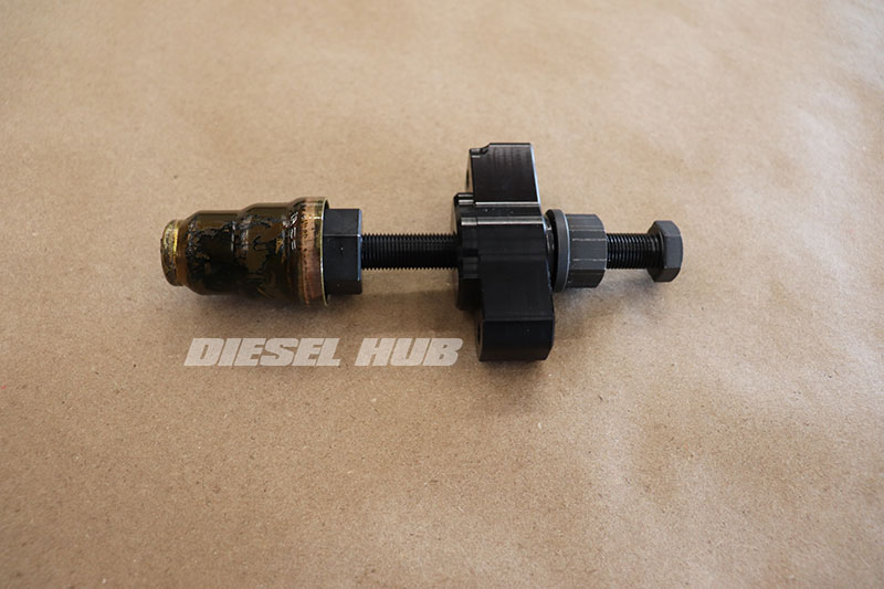
A professional combination sleeve puller and installation tool runs several hundred dollars, but there are some very economic options available at a fraction of the cost. The original Ford puller (OTC/Rotunda 014-00934-1) is comprised of an off-the-shelf 1-1/4 x 20 tap and a proprietary fixture that allows the tap to be attached to a slide hammer. The tap is threaded into the sleeve and with a quick whack of the hammer, it is removed from the cylinder head.
The original Ford installation tool (OTC/Rotunda 014-00934-4) is a fixture machined to match the internal geometry of a sleeve. It is inserted into the new sleeve and driven into the cylinder head opening with a mallet. A distinct "pop" into place and a dull thud indicates that they have been driven to the proper depth.
The greatest challenge with this tool type is that a slide hammer doesn't fit into the engine compartment to service the rear-most cylinders, making this a head-off operation. The solution is a tool that grabs the sleeve in the same way, but pulls it out by means of forcing screw. Economical tool options are provided in table 1 above.
Injector Sleeve Removal
Click any thumbnail to view fullsize, detailed image

- Disconnect both negative battery cables.
- Locate the drain valve (petcock) at the lower, driver side corner of the radiator.
- Drain the engine coolant from the radiator into a suitable container. Good engine coolant drained into clean vessels can be reused.

- Locate the engine block coolant drain plug on the passenger side. It is hidden from view and easier to access with the starter motor removed. Removing the starter is (3) bolts that require a 17 mm socket and various extensions. You may be able to position the starter out of the way without disconnecting any of its wire.
- Position a suitable container beneath the block drain, then remove the plug (fastener head size/type may vary).
- When coolant stops draining from the block, reinstall the plug and starter motor.

- Locate the engine block coolant drain plug on the driver side. It is positioned behind the rear oil cooler header; do not confuse it with the oil port located below it.
- Position a suitable container beneath the block drain, then remove the plug (fastener head size/type may vary).
- When coolant stops draining from the block, reinstall the plug.
Note - failure to properly drain the cooling system, including the engine block drains, will result in engine coolant flooding the combustion chamber and possibly the cylinder head once an injector sleeve is removed from that bank.
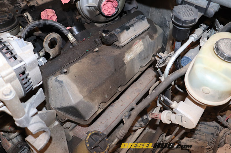
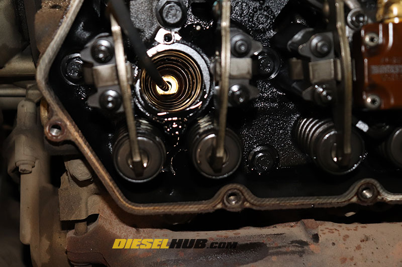
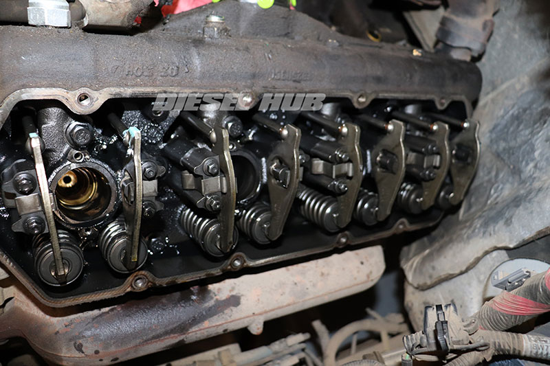
- Remove the valve covers; see valve cover removal for additional guidance, if necessary.

- Disconnect the glow plugs and fuel injectors from the appropriate under valve cover harness connectors.
- Remove the valve cover gasket/UVCH and set aside.

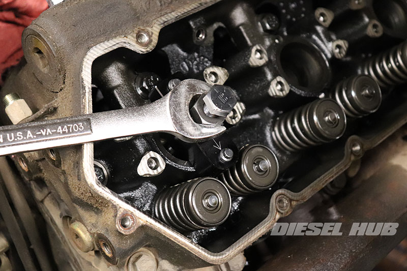
- Remove the pair of oil gallery drain plugs from each cylinder head with a 1/8 inch hex (Allen) key or driver.
- Note - the oil rail drain plugs are located between cylinders 1 and 3, 5 and 7 on the driver side and cylinders 2 and 4, 6 and 8 on the passenger side.

- In order to remove as much oil as possible from the system, use a fluid extraction tool to evacuate the high pressure oil galleries through each drain plug opening.

- Remove each injector; see 7.3 Power Stroke injector removal for additional guidance.
- If injectors 7 and 8 (rearmost) are removed first, most of the fuel and oil that drains will end up in these two cylinders. This is beneficial in that there will be less fluids to evacuate from subsequent cylinders.
- As a fuel injector is removed, immediately begin extracting fuel and oil that enters the sleeve/combustion chamber.
- Do not allow fuel to sit in the combustion chamber, evacuate each combustion chamber as much as possible as each injector is removed.
- Remove the glow plugs from each cylinder with a 10 mm deep socket.
- Plug each sleeve with a clean shop rag to prevent debris infiltration during the removal process.

- Place the sleeve puller into the injector cavity with the forcing screw retreated.
- If applicable, fix the tool to the cylinder head using the injector hold-down bolt holes.

- Rotate the forcing screw clockwise to engage the tap with the injector sleeve.
- Once the tap has engaged the sleeve, rotate the forcing screw several rotations so that that threads are cut into sleeve.
- Do not overtighten or tap too deeply as this expands the brass sleeve, making it more difficult to pull.
- Rotate the lower nut clockwise while preventing the forcing screw from rotating to pull the sleeve out (note - actual operation may depend on tool choice).
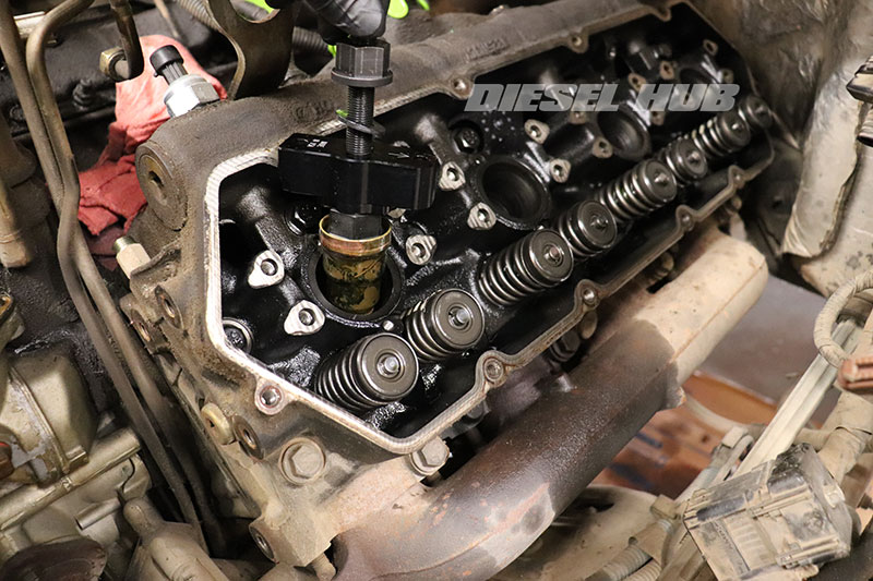
- Pull the tool from the injector bore with the sleeve attached.
- Clean the cylinder head bore with an appropriate brush. The goal is to break loose and clean away any retaining compound and buildup from the sealing surfaces.
- Once again clear oil and fuel out of the injector bore/combustion chamber. Residual engine coolant may also seep into the chambers once the sleeve is removed.
- Repeat the process to remove all 8 sleeves.
- The old injector sleeves may be difficult to remove from the threaded portion of the tool. If necessary, chuck the tool in a vice and unthread the sleeve with vice grips, channel locks, or even large pliers.
Injector Sleeves Installation

- Place the new injector sleeve onto the tool fixture; do not use the threaded portion of the tool to install cups!
- An o-ring on the tool fixture holds the sleeve in place during installation.

- Apply Loctite 620 retaining compound around the top and bottom circumference of the new sleeve (as pictured).
- The location that the retaining compound is applied is strategic.
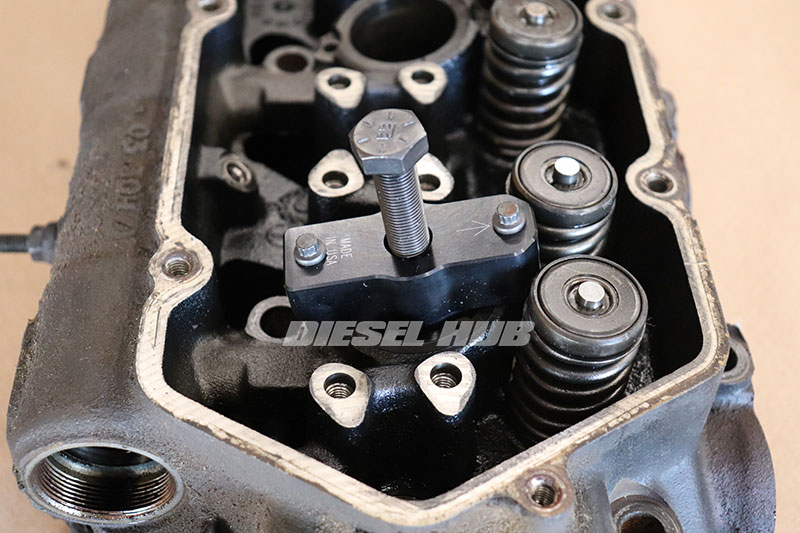
- Slide the sleeve into the cylinder head bore without getting retaining compound in areas it should not be.
- For press-in type tools, fix the tool to the cylinder head and drive the forcing screw downwards until the sleeve "pops" into place, signaling that it has bottomed out.
- For drive-in type tools, tap the top of the tool with a dead-blow hammer to "pop" the sleeve into place, signaling that it has bottomed out. Excessive force is not necessary, start light and increase pressure to get a feel for the force needed.

- Promptly clean any excess retaining compound from the bore as it could impede injector sealing.
- Repeat for all 8 cylinders.
- Allow the retaining compound to cure for 24 hours, then reinstall each fuel injector with new seals.
After the sleeves and injectors are installed, it is necessary to verify that the combustion chambers are properly evacuated. It takes very little fluid to hydro-lock a cylinder and although steps have been taken thus far to remove fluids from the combustion chambers it is absolutely imperative to force any remaining fluids out. All glow plugs must be removed for the duration of this process.

- Ensure that the valvetrain can move freely & unobstructed, then loosely install both valve covers with a few fasteners; the gaskets and valve cover harnesses are not necessary at this time. The glow plugs should still be removed at this time.
- Remove any coverings (rags, plugs, caps, etc) from the turbocharger inlet and any similar passages that must be unobstructed while the engine is cranked over.
- Reconnect the negative battery cables and crank the engine over for several seconds, then pause. Repeat 2 to 3 more times, then disconnect the battery cables and remove the valve covers once more.
- The engine will not start because the fuel injectors are not currently connected to the engine wiring harness. Any fluid remaining in the cylinder heads has be evacuated through the glow plug holes.

- Reinstall the glow plugs, valve cover gaskets/UVCH, and the valve covers.
- From here, reassemble the remaining components in reverse order. Don't forget to refill the cooling system.
- Change the engine oil and lube oil filter; coolant, fuel, and dirty oil has infiltrated the crankcase and contaminated the engine oil.
- Clear any DTCs that were set while cranking the engine over with the injector harnesses disconnected.
- Prime the fuel and oil system before starting the engine. Check fluids frequently to ensure one or more of the new injector sleeves is not leaking.
Torque Chart
| Component | Torque, in-lbs |
|---|---|
| Injector hold down bolts | 120 |
| Injector oil deflector spout | 106 |
| Glow plug | 124 |
| Valve cover bolts | 97 |

