Applicable Models:
1999 - 2003 Ford F-250, F-350, F-450, F-550 Super Duty
2000 - 2003 Ford Excursion
1998 - 1999 Ford Econoline E-350
2000 - 2003 Ford F-650, F-750
2000 - 2003 Econoline E-350, E-450, E-550
Applicable Engine(s):
7.3 liter Power Stroke V-8 (7.3 DIT)
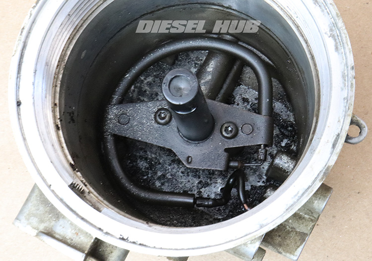
"Fuel bowl" is synonymous with the fuel filter housing, which is responsible for fuel filtration, water separation, and pressure regulation. The fuel restriction sensor, water-in-fuel sensor, and fuel heater are also incorporated into the filter housing. A drain valve mounted at the rear of the housing allows water to be drained off or the bowl to be drained for service/repairs. It is centrally located in the engine valley between the high pressure oil pump and turbocharger.

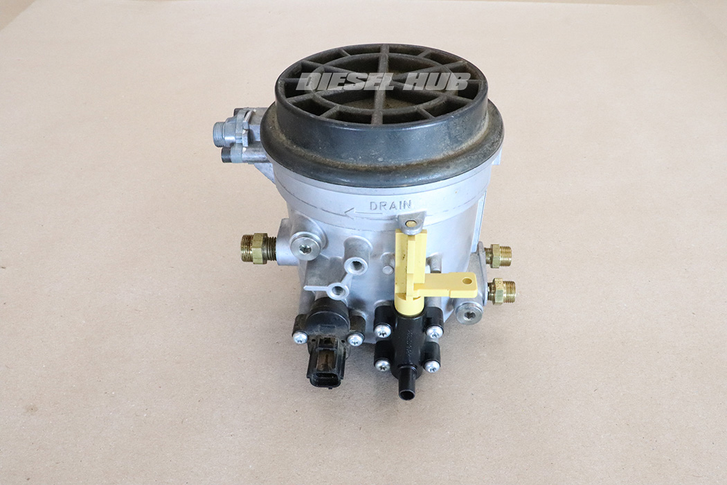
The filter housing on 1998 to 2003 engines that utilize an electric fuel pump is significantly smaller and simpler than previous designs, but it also seals many of its components with o-rings. As these o-rings age, they can deteriorate, swell, become brittle, and develop leaks. Fortunately, the assembly is serviceable and can be rebuilt with new seals. Rebuilding the filter housing is significantly cheaper than replacing it and replacement is generally only warranted when the aluminum housing is cracked. New life can be bestowed to the fuel bowl with an economical rebuild kit.
Fuel Bowl Parts
| Component | Part Number(s) | Remarks |
|---|---|---|
| Fuel bowl seal kit | DP-1642K | [1] |
| Pressure regulator kit | Ford F81Z-9B249-BB | [2],[3] |
| Water-in-fuel sensor | Ford F81Z-9J294-BA | [3] |
| Fuel bowl heater | Ford F81Z-9J294-AA | [3] |
| Drain valve assembly | Ford F81Z-9A153-AA | [3] |
| Standpipe | Ford F81Z-9236-AA | [3] |
| Pressure test adapter | DP-160501 | [4] |
| Fuel filter | Motorcraft FD-4596 | [5] |
| Fuel bowl cap | Ford F81Z-9G270-BA | [3] |
[1] - Includes the (11) o-rings necessary to completely reseal the housing, thread sealant for the brass fittings, (4) compressions sleeves for the inlet, tank return, and outlet fittings, and new drain valve hose
[2] - Includes new spring, poppet, bushing, and relevant o-rings; check fuel pressure before removing the fuel bowl to determine whether a new pressure regulator is required or the old one can be reused
[3] - If properly functioning and not damaged, reuse this component
[4] - Takes the place of one of the hex-headed plugs in the filter housing
[5] - A new fuel filter is mandatory after rebuilding the unit
Proper O-ring Installation
While there are some rare occasions where o-rings are installed dry, they are typically generously coated in clean engine oil before installed on engine and fuel system components. This performs several functions, including:
- Ensures smooth installation with minimized binding action that could tear or damage o-ring
- Minimizes residual stresses in the installed o-ring by limiting twisting and binding, allowing the o-ring to rest in a more "natural" orientation
- Provides lubrication between the o-ring and sealing surfaces
O-rings that are installed dry are more likely to bind, twist, and become pinched. Applying motor oil before installation is the best way to safeguard the integrity of the seal.
Cleaning Tips & Techniques
There may be sediment built up in the bottom of the filter housing (figure 2 below). This is fairly common and occurs because fuel from the tank is strained, but not filtered. Fine sediment gets pumped from the tank and enters the filter housing where it settles to the bottom (as it is supposed to). After the filter housing is disassembled, all components should be thoroughly cleaned.
The cast aluminum housing and pressure regulator cap can be cleaned with solvents (brake cleaner, carb & choke cleaner, mineral spirits, etc) or most water-based degreasers (i.e. Simple Green). Note that some water-based degreasers may not be compatible with aluminum so it is important to verify compatibility before using these products. Diesel fuel also makes an excellent degreaser and these aluminum parts can be soaked overnight to break free stubborn deposits.
Do not use any of the aforementioned solvents on any of the plastic or rubber components that are to be reused. Plastic components can be washed with water or, preferable, electrical connector cleaner (i.e. CRC electronic cleaner) because it is a very mild solvent that will not dissolve plastics and is also safe to use on the water-in-fuel sensor and fuel heater element.
Disassembly & Assembly Procedures
Click any thumbnail to view fullsize, detailed image
- Drain, then remove the fuel bowl from the engine.
- Remove the cap, followed by the fuel filter.
- Set the fuel bowl upside down on a few shop towels and allow it to drain completely before attempting to disassemble it.
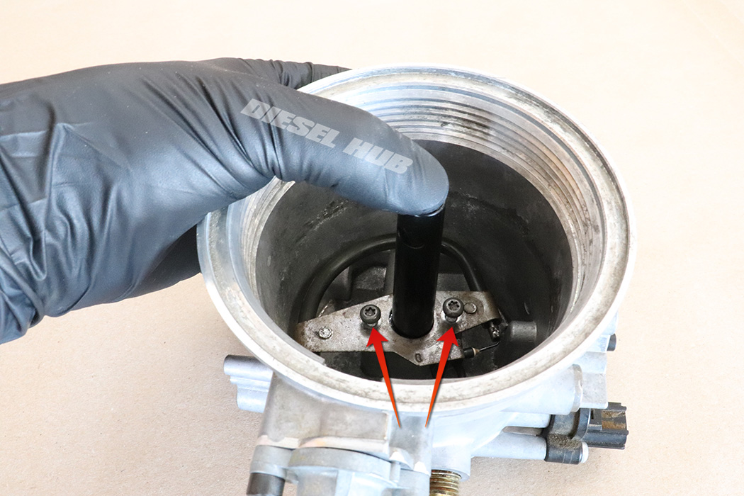
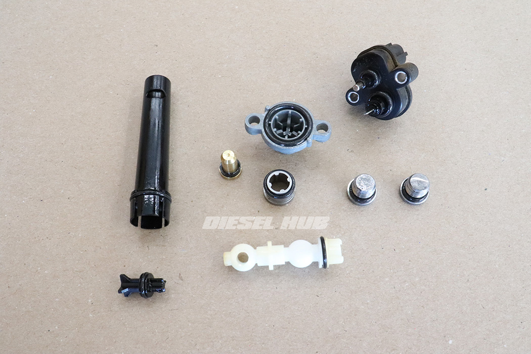
- Note that the standpipe has an integral spring-loaded check valve and is secured to the base of the fuel bowl by the fuel heater.
- While securing the standpipe with one hand, remove the (2) machine screws securing the fuel heater with a T20 Torx driver.
- With both screws removed, let the fuel heater and standpipe rest and continue to the next step.
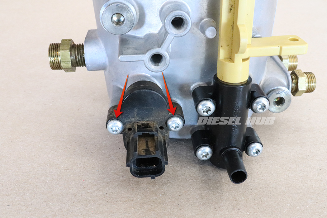
- Remove the (2) machine screws that secure the water-in-fuel sensor (which also contains the thermostatic device for the fuel heater element) with a T20 Torx driver.
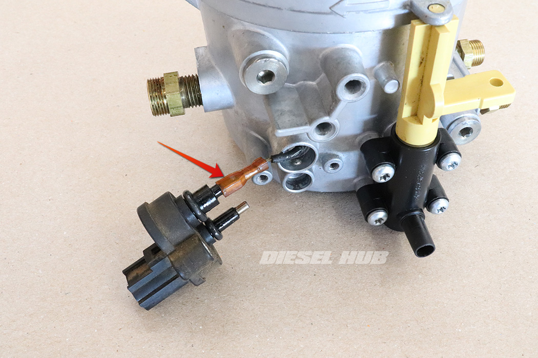
- Carefully pull the water-in-fuel sensor out of the housing while maneuvering the fuel heater electrical connector out with it.
- Disconnect the fuel heater electrical connector.
- Remove the fuel heater element and standpipe.
- The water-in-fuel sensor is sealed to the housing with (2) o-rings.

- Remove the (4) machine screws securing the drain valve assembly to the filter housing with a T20 Torx driver.
- Separate the drain valve assembly from the filter housing.
- The drain valve is sealed to the housing with (2) o-rings.

- Note that the pressure regulator housing cap is under spring pressure.
- While securing the pressure regulator cap with one hand, remove the (2) machine screws securing it to the housing with a T27 Torx driver.
- When the screws have been removed completely, slowly release your grip and allow the force on the spring to be relieved.
- Remove the fuel pressure regulator spring and poppet.
- The pressure regulator cap seals to the housing with (1) o-ring.
- Inspect the pressure regulator poppet - if the seal is not damaged, do not attempt to remove it; the poppet can be reused.

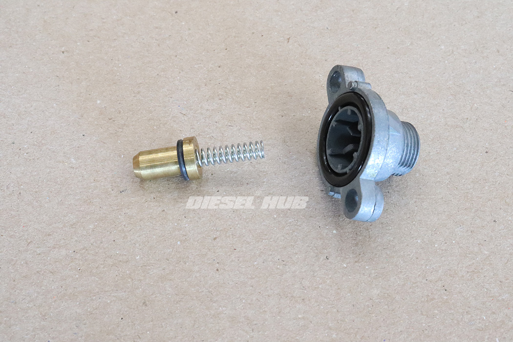
- Remove the fuel pressure regulator bushing by pushing it through the housing with a small socket.
- If there is significant resistance, it is because the bushing is sealed to the housing by an o-ring that may have become stiff and swollen.

- Remove both access plugs from the rear of the housing with a 3/16 inch hex key (Allen).
- Each plug is sealed to the housing with (1) o-ring.
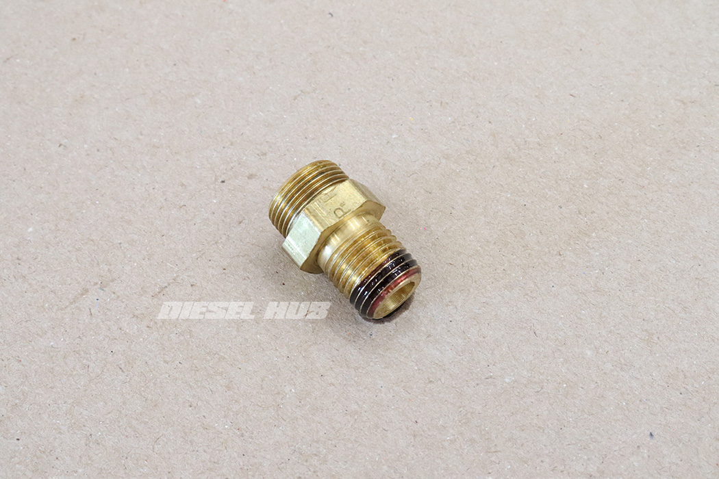
- Optional - if desired, remove the brass fuel inlet and outlet fittings. The large inlet fitting requires an 11/16 inch socket and the smaller outlet fittings accept a 9/16 inch socket. This is only necessary if you wish to reseal these fittings (recommended).

- Disassemble the standpipe by pushing the face of the check valve down through the tube.
- The components have been laid out in their proper order in the image at left.

- Remove the old o-rings from the standpipe tube and the lower bushing.

- Rotate the drain valve until the flat spots on the mechanism (white component) are visible on the backside. If the domed component of either ball valve is visible, it will not slide out of the housing.

- Thread one of the smaller Torx screws into the plastic bushing at the tip of the drain valve and pull it out.
- Carefully retrieve the small plastic ball that lies beneath the bushing.
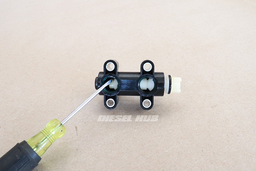
- Pull the valve stem (white) out of the housing (black).
- A small pick or flathead screwdriver can be used to pry from the lower section, but do not mar any of the sealing surfaces in the process.

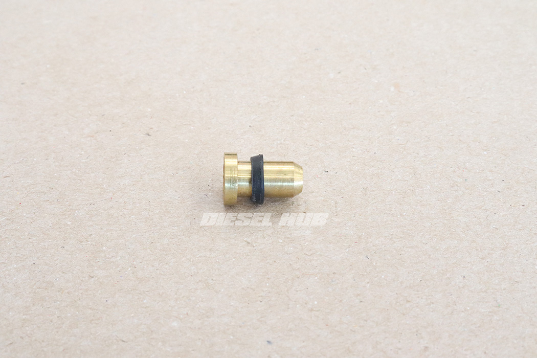
- Remove the o-ring that seals the ball valve stem to the drain valve housing.

- Remove the o-rings from the pressure regulator cap, water-in-fuel sensor, drain plugs, and pressure regulator bushing.
- Thoroughly clean all components. Recommendations have been provided in the section above.
- Do not clean plastic components with solvents such as brake cleaner!
- Inspect the seal on the pressure regulator poppet. This is a special beveled o-ring that is only serviced in the Ford pressure regulator kit (Ford F81Z-9B249-BB). If it is good condition, there is no reason to replace it.
- If the pressure regulator components are being replaced coat the poppet seal with clean motor oil and install it as pictured, specifically noting the direction of the bevel.
- If the brass inlet and outlet fittings have been removed, apply an appropriate sealant to the threads and reinstall them.
- These fittings use tapered threads and will crack the housing if they are over-torqued.
- Install new o-rings on the standpipe components, pressure regulator cap, water-in-fuel sensor, housing plugs, drain valve, and the pressure regulator poppet bushing (seat).
- Generously coat each new o-ring in clean motor oil before installation.

- Reassembly the drain valve assembly in reverse order. The ball valve can only be installed into the housing if the flats are oriented corrected.
- You will note that the o-ring "pops" into place when correctly seated.
- Do not forget to install the small plastic ball, followed by the bushing.

- Generously coat the drain valve housing o-rings in clean motor oil.
- Install the drain valve housing o-rings.
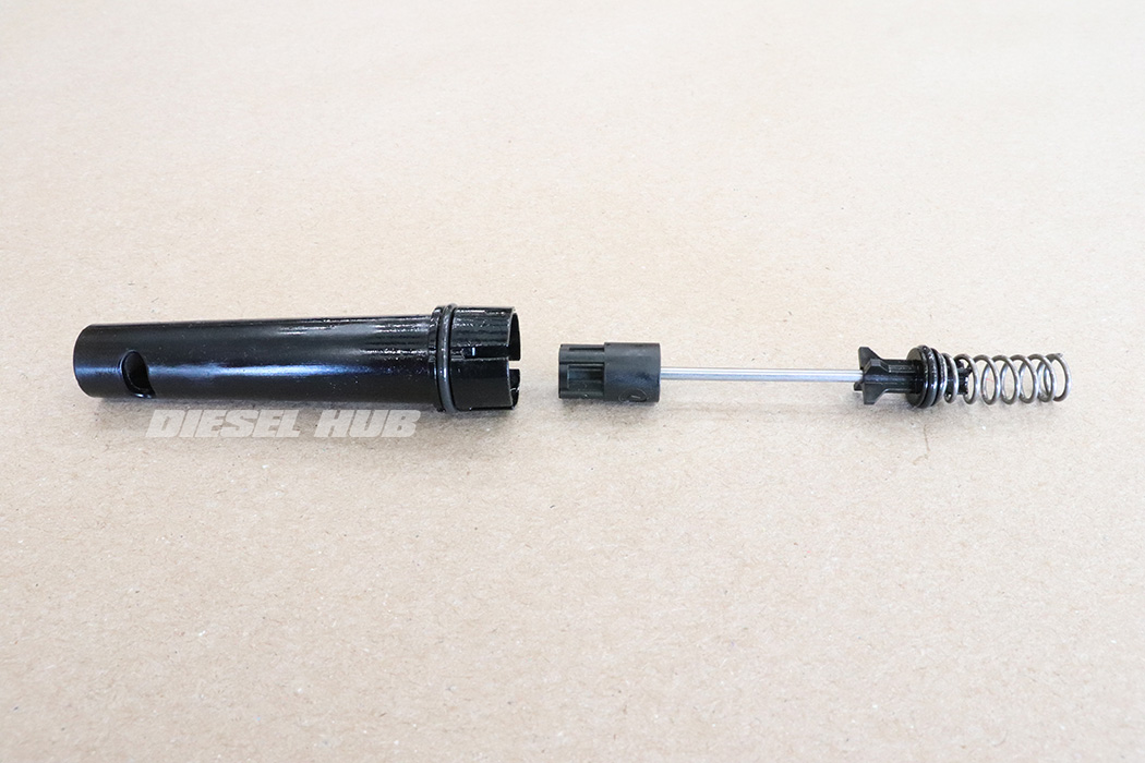
- Reassembly the standpipe check valve.
- The correct orientation is depicted in the image at left.
- Note that the metal rod slides into holes in the plastic components on either end.

- Position the drain valve handle, then reinstall the drain valve to the housing.
- The handle can only be installed in the "correct" manner, thus you may have to rotate the valve to find the proper orientation.
- Do not overtighten the drain valve mounting bolts.

- Install the fuel pressure regulator bushing (seat). You should note that the o-ring "pops" into place when it is properly seated.
- Install the pressure regulator poppet valve, followed by the spring.

- Install the pressure regulator cap and use it to compress the spring.
- The spring must be centrally located in the cap. You can look into the face of the cap to verify that the spring is not caught on one of the ribbed features.
- Note that the cap has two dowel pins approximately 180 degrees apart that must line up with the corresponding holes in the housing.
- When the cap is fully compressed and properly aligned, install the bolts and tighten snug. Do not use the bolts to compress the spring.

- Install the standpipe, followed by the fuel heater element.
- As you place the fuel heater element into the bowl, maneuver the electric connector through the correct opening.
- Plug the fuel heater connector into the thermostat terminal.
- Install the water-in-fuel sensor; do not overtighten the screws.
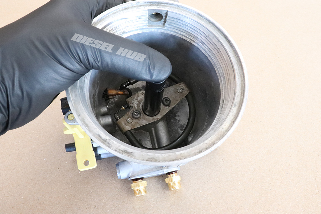
- Align and secure the standpipe downwards.
- Maneuver the heater into place and install the screws.
- While maintaining downward pressure on the standpipe, tighten the fuel heater screws completely.

- Verify that the standpipe check valve is functioning properly by pushing it downwards with a flathead screwdriver, hex key, etc (do not use a sharp object).
- The check valve should spring back to the closed position after being pushed down.
- The filter housing is now ready for a new filter and reinstallation. Do not forget to use new compression sleeves on the inlet/outlet fittings and a new drain valve hose connection.

